bullfrog spa owner’s manual

Welcome to the Bullfrog Spa Owners Manual! This guide provides essential information for safe and enjoyable spa use, covering installation, maintenance, and troubleshooting tips. Read it carefully to ensure optimal performance and longevity of your spa.

Importance of Reading the Manual

Reading the Bullfrog Spa Owners Manual is crucial for safe and efficient spa operation. It provides detailed guidelines for installation, maintenance, and troubleshooting, ensuring optimal performance. Proper understanding of the manual prevents damage to equipment and enhances user safety. Additionally, it outlines warranty terms and conditions, helping you avoid voiding coverage. By following the manual, you can extend the spa’s lifespan and enjoy a hassle-free experience. Regular updates and tips are included to keep your spa in peak condition.

Quick Reference Guide for Installation and Maintenance

This guide provides key steps for installing and maintaining your Bullfrog Spa. Ensure the site is level and sturdy to support the spa’s weight. Check electrical requirements and connect properly. Regularly clean filters and test water chemistry. Drain and refill water as recommended. Inspect equipment for damage and ensure air vents are unblocked to prevent overheating. Keep the spa cover on when not in use for energy efficiency and safety. Refer to the manual for detailed procedures and troubleshooting tips.

Safety Precautions and Warnings

Always follow safety guidelines to prevent accidents. Supervise children closely, keep the spa cover locked when not in use, and avoid hazards that could cause overheating or damage.

Risk of Damage to Spa or Equipment

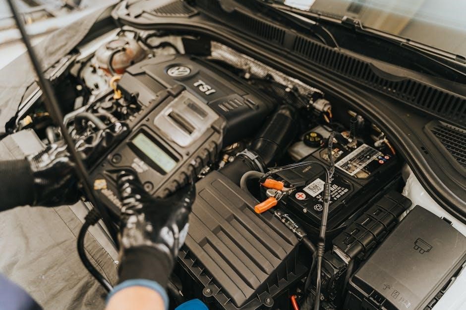
Improper maintenance or blocking air vents can cause overheating and damage to your spa or equipment. Regular maintenance, as outlined in the manual, reduces these risks. Never use unapproved parts, as they may void your warranty or lead to malfunctions. Always ensure proper ventilation and avoid exceeding weight limits to protect your spa. Following guidelines ensures longevity and safety for your Bullfrog Spa investment.

Proper Spa Location and Foundation Requirements

Ensure your spa is placed on a sturdy, level foundation that can support its weight when filled. Concrete or reinforced decking is recommended. The site must be even and well-drained to prevent water accumulation. Avoid placing the spa near hazardous materials or overhead power lines. The foundation should be designed to bear the combined weight of the spa, water, and occupants. Always consult local building codes and your Bullfrog Spa dealer for specific requirements to ensure a safe and stable installation.

Installation and Setup

Install your Bullfrog Spa on a level, sturdy surface. Follow the manual’s guidelines for site preparation and delivery. Ensure proper electrical connections and plumbing setup for safe operation.

Site Selection and Preparation

Select a flat, stable site for your spa, ensuring it can support the filled weight. Choose a location with good drainage and easy access to power. Avoid areas prone to water pooling or direct sunlight. Ensure the site is level to prevent uneven settling. Clear the area of debris and obstructions. If placing on a deck, verify it can handle the weight. Proper preparation ensures safe installation and optimal performance of your Bullfrog Spa.

Delivery and Placement Considerations

Measure the delivery path and ensure clearance for your spa’s dimensions. Use a sturdy dolly to transport the spa, adding the cart’s height (typically 6 inches) to the spa’s height for total clearance. Ensure the site is clear of debris and obstructions. Protect the area from damage during placement; If unsure about delivery logistics, consult your authorized Bullfrog Spas Dealer for assistance. Proper delivery and placement are crucial for safe installation and optimal spa performance.

Maintenance and Care

Regular maintenance ensures your spa remains clean and functional. Clean filters weekly, check chemical levels, and inspect the cover when not in use for optimal performance and safety.

Regular Maintenance Tasks

Regular maintenance is crucial for optimal spa functionality and safety. Clean filters weekly, check chemical levels, and inspect the cover when not in use. Ensure proper water circulation by maintaining adequate flow rates. Regularly test and balance water chemistry to prevent damage and ensure a clean environment. Refer to the manual for detailed instructions on maintaining your Bullfrog Spa. Adhere to recommended schedules to prevent equipment damage and extend the spa’s lifespan. Proper care ensures years of enjoyable use.

Chemical Usage and Water Care

Proper chemical usage and water care are essential for maintaining a safe and enjoyable spa experience. Regularly test and balance pH and bromine levels to ensure optimal water quality. Shock the water weekly to eliminate contaminants and maintain clarity. Always follow the recommended dosage for chemicals to avoid overuse, which can damage equipment or cause skin irritation. Clean filters regularly and replace them as needed to maintain proper water circulation. Refer to the manual for specific guidelines on chemical usage and water care routines.

Troubleshooting Common Issues

This section helps identify and resolve common spa malfunctions, such as heater issues or pump failures. Regular maintenance and proper chemical levels can prevent many problems. Always refer to the manual for specific solutions or contact authorized Bullfrog Spa support for assistance. Addressing issues promptly ensures optimal spa performance and longevity.

Identifying and Resolving Spa Malfunctions

Common issues like heater malfunctions or pump failures can often be resolved by checking power supply, ensuring proper water levels, and cleaning filters. Error codes on the control panel can help diagnose problems; Refer to the troubleshooting section of your manual for specific solutions. If issues persist, contact Bullfrog Spa customer support or an authorized dealer for professional assistance. Regular maintenance and timely repairs will ensure your spa operates smoothly and safely for years to come.

Bullfrog Spas offers comprehensive customer support to ensure your spa experience remains enjoyable. For any issues, contact their support team via phone, email, or online chat. Authorized dealers provide local assistance, including repairs and genuine parts; Their expertise ensures timely resolutions and maintains your spa’s warranty. Whether troubleshooting or needing maintenance, rely on Bullfrog’s dedicated support network to keep your spa in optimal condition. Visit their official website for contact details and additional resources.

Additional Features and Accessories

Customer Support and Dealer Assistance

Bullfrog Spas provides exceptional customer support and dealer assistance to ensure a seamless spa ownership experience. Their dedicated team offers expert guidance, troubleshooting, and repair services. Authorized dealers supply genuine parts and professional advice, while online resources and manuals are available for quick reference. Whether you need maintenance tips or technical help, Bullfrog’s support network is designed to keep your spa running smoothly and enhance your enjoyment.

Stereo Systems and Audio Equipment Operation

Bullfrog Spas offer advanced stereo systems, including models like Gecko and JBL, designed for seamless integration. The manual provides detailed operation guides, covering installation, maintenance, and troubleshooting. Proper setup ensures optimal sound quality and durability. Regular maintenance tasks, such as cleaning speakers and updating software, are outlined. Troubleshooting common issues like connectivity problems is also covered. Always follow manufacturer guidelines to prevent warranty voidance and ensure safe use.

Spa Cover Dimensions and Care

Ensure your Bullfrog spa cover fits perfectly by referring to the provided dimensions in the manual. Regularly clean the cover with mild detergents to maintain its condition. Store it in a dry, protected area when not in use. Proper care extends the cover’s lifespan and ensures energy efficiency. Always lock the cover to prevent accidents and maintain safety. Follow the manual’s guidelines for precise measurements and care routines to keep your spa secure and well-maintained.

Warranty Information

Understand your Bullfrog Spa warranty to ensure coverage and avoid issues. Proper installation and maintenance, as outlined in the manual, are crucial for warranty validity and preventing voidance.

Understanding Your Spa Warranty

Your Bullfrog Spa warranty provides coverage for defects in materials and workmanship. The warranty period varies by component, with detailed terms outlined in the manual. Proper installation and maintenance are essential to uphold warranty validity. Unauthorized modifications or improper use can void coverage. Refer to your manual or consult an authorized Bullfrog Spa dealer for specific terms and conditions. Regular maintenance ensures optimal performance and prevents issues that may not be covered under warranty.

Voiding Warranty and Preventing Issues

To avoid voiding your Bullfrog Spa warranty, ensure all installations and repairs are performed by authorized personnel. Unauthorized modifications or using non-approved parts can invalidate coverage. Proper maintenance, as outlined in the manual, is crucial to prevent issues and maintain warranty validity.

Failure to follow guidelines may result in denied claims. Always refer to your manual or consult an authorized Bullfrog Spa dealer for any concerns or repairs to ensure your spa remains under warranty and functions optimally.

Final Tips for Safe and Enjoyable Spa Use

  • Always supervise children when the spa is in use to ensure their safety.
  • Regularly test and adjust chemical levels to maintain clean, safe water.
  • Keep the spa cover securely locked when not in use to prevent accidents.
  • Avoid using the spa during extreme weather conditions like thunderstorms.
  • Clean the filter regularly to ensure optimal performance and water quality.
  • Adjust jet settings for personal comfort and relaxation.
  • Store spa chemicals in a cool, dry place away from children and pets.

2010 honda odyssey owners manual

Welcome to the 2010 Honda Odyssey Owners Manual, your comprehensive guide to understanding and maintaining your vehicle. This manual provides essential information on features, maintenance, and troubleshooting to ensure safe and enjoyable driving. Keep it in your vehicle for quick reference.

1.1 Purpose and Importance of the Manual

The 2010 Honda Odyssey Owners Manual is designed to help you understand your vehicle’s features, operation, and maintenance. It provides essential information for safe driving, proper usage of controls, and routine maintenance to ensure optimal performance. Referencing this manual regularly helps protect your investment and ensures trouble-free driving experiences. Keep it handy for quick access to vital details.

1.2 How to Use the Manual Effectively

Start by reviewing the table of contents to navigate the manual easily. Focus on key sections like driving controls, maintenance schedules, and troubleshooting. Refer to specific pages for detailed instructions and ensure you understand safety precautions. Regularly revisit the manual to stay informed about your vehicle’s features and optimal operation. This will help you maximize performance and longevity.

Vehicle Identification and Specifications

This section provides details about your vehicle’s identification, including the VIN location and key specifications like engine type, transmission, and features, essential for maintenance and reference.

2.1 Vehicle Identification Number (VIN) and Its Location

The Vehicle Identification Number (VIN) is a unique 17-character code that identifies your 2010 Honda Odyssey. It can be found on the driver’s side dashboard near the windshield or on the driver’s doorjamb. This number is essential for vehicle registration, insurance, and maintenance records, ensuring accurate identification of your vehicle’s make, model, and production details.

2.2 Key Specifications of the 2010 Honda Odyssey

The 2010 Honda Odyssey features a 3.5-liter, SOHC i-VTEC V-6 engine with Variable Cylinder Management (VCM) for enhanced fuel efficiency. It is paired with a 5-Speed Automatic Transmission, offering smooth performance. Available in LX, EX, EX-L, and Touring trims, the Odyssey seats up to eight passengers. The EX-L and Touring models include premium features like a leather-trimmed interior and advanced entertainment systems.

Safety Precautions and Guidelines

Safety is a top priority in the 2010 Honda Odyssey. Essential features include advanced airbags, anti-lock brakes, and electronic stability control. Always wear seatbelts correctly and ensure no objects obstruct airbag deployment. Regular checks of these systems are crucial for optimal safety and performance. Adhere to all maintenance schedules to ensure reliability.

3.1 Essential Safety Features of the 2010 Honda Odyssey

The 2010 Honda Odyssey is equipped with advanced safety features, including a multi-angle rearview camera, electronic stability control, and a comprehensive airbag system with side and curtain airbags. These features, combined with anti-lock brakes and a rigid body structure, enhance driver and passenger protection. Regular maintenance of these systems ensures optimal performance and safety on the road.

3.2 Proper Use of Seatbelts and Airbags

All passengers must wear seatbelts correctly, ensuring the lap belt is snug and the shoulder belt is across the chest. Airbags deploy in collisions, but they are most effective when seatbelts are worn. Never place an infant seat in front of an active airbag. Always follow the manual’s guidelines for proper seatbelt and airbag use to ensure maximum safety protection for all occupants.

Driving Controls and Instruments

The 2010 Honda Odyssey features a user-friendly dashboard with essential controls and instruments. The instrument cluster displays vital information, while intuitive controls ensure a smooth driving experience.

4.1 Overview of the Dashboard and Instrument Cluster

The 2010 Honda Odyssey’s dashboard is designed for driver convenience, featuring a central instrument cluster with a speedometer, tachometer, and fuel gauge. Additional displays include temperature, odometer, and warning lights. The layout ensures easy access to controls for climate, audio, and navigation systems, enhancing both functionality and comfort during your journey.

4.2 Understanding the Gear Shift and Transmission Controls

The 2010 Honda Odyssey features a 5-Speed Automatic Transmission, controlled by a gear shift located on the center console. The shift includes positions for Park, Reverse, Neutral, Drive, and manual gear selection. Proper use of the gear shift ensures smooth acceleration and optimal fuel efficiency. Refer to the manual for maintenance schedules to keep the transmission functioning at its best.

Maintenance and Servicing Schedule

Regular maintenance is crucial for the 2010 Honda Odyssey. Follow the schedules in this manual to ensure optimal performance, prevent issues, and preserve your vehicle.

5.1 Recommended Maintenance Intervals for the 2010 Honda Odyssey

The 2010 Honda Odyssey requires regular maintenance at specific intervals to maintain performance. Oil changes are recommended every 5,000 to 7,500 miles, while tire rotations should occur every 7,500 miles. Brake pads and fluids should be inspected every 15,000 miles. Additionally, the spark plugs should be replaced every 30,000 miles. Following these intervals ensures reliability and longevity of your vehicle.

5.2 Importance of Regular Fluid Checks and Replacements

Regular fluid checks and replacements are crucial for maintaining the 2010 Honda Odyssey’s performance and longevity. Engine oil, coolant, transmission, and brake fluids must be inspected and changed as per the recommended schedule. Neglecting these can lead to overheating, reduced braking efficiency, or engine damage. Always use Honda-approved fluids to ensure compatibility and optimal functionality.

Features and Accessories

The 2010 Honda Odyssey offers premium features like leather-trimmed interiors, Honda Satellite-linked Navigation, and DVD rear entertainment. Accessories include a 3.5-liter V-6 engine with VCM, enhancing fuel efficiency and performance, ensuring a comfortable and convenient driving experience.

6.1 Premium Features Available in the 2010 Honda Odyssey

The 2010 Honda Odyssey offers premium features such as a leather-trimmed interior, a Honda Satellite-linked Navigation System, and a DVD rear entertainment system for passenger enjoyment. These features enhance comfort, convenience, and entertainment, making the vehicle ideal for family trips and daily commuting. The Odyssey also includes a 3.5-liter V-6 engine with Variable Cylinder Management (VCM) for improved fuel efficiency.

6.2 Operating the Honda Satellite-Linked Navigation System

The Honda Satellite-Linked Navigation System in the 2010 Odyssey provides voice-guided directions and real-time traffic updates. Use the touchscreen to input destinations, view maps, and access points of interest. The system also integrates with the audio controls for seamless entertainment and navigation. Refer to the manual for detailed instructions on customizing settings and updating maps for optimal performance.

Transmission and Performance

The 2010 Honda Odyssey features a 5-speed automatic transmission, designed for smooth shifting and optimal fuel efficiency. Its robust V6 engine delivers strong acceleration and responsive handling, ensuring a balanced blend of power and efficiency for both city driving and highway cruising.

7.1 Overview of the 5-Speed Automatic Transmission

The 2010 Honda Odyssey is equipped with a smooth and fuel-efficient 5-speed automatic transmission. Designed for optimal performance, it features gear ratios that enhance both city driving and highway cruising. The transmission seamlessly adapts to varying conditions, ensuring responsive acceleration and steady power delivery. Its reliability and precision contribute to the Odyssey’s reputation for dependable and enjoyable driving experiences.

7.2 Gear Ratios and Their Impact on Performance

The 2010 Honda Odyssey’s 5-speed automatic transmission features gear ratios optimized for balanced performance and fuel efficiency. Lower gears provide strong acceleration for city driving, while higher gears maintain smooth power delivery at higher speeds. This configuration enhances overall driving dynamics, ensuring responsive acceleration and steady cruising, making the Odyssey both versatile and efficient for various driving conditions.

Troubleshooting Common Issues

This section helps identify and address common problems with your 2010 Honda Odyssey. Learn how to diagnose issues, reference warning lights, and determine when professional assistance is needed; Regular maintenance can often prevent these problems, ensuring your vehicle runs smoothly and reliably over time.

8.1 Identifying and Addressing Warning Lights on the Dashboard

Your 2010 Honda Odyssey’s dashboard warning lights alert you to potential issues. Refer to this section to identify each light’s meaning, understand its urgency, and take appropriate action. Consult the manual for guidance on resolving common issues or when professional assistance is required to ensure your safety and maintain your vehicle’s performance. Always address warnings promptly.

8.2 Common Problems and DIY Solutions

Common issues with the 2010 Honda Odyssey include low fluid levels, worn air filters, and battery maintenance. Regular fluid checks and replacements can prevent engine damage. Replacing the air filter improves fuel efficiency and performance. For battery care, ensure terminals are clean and secure. Addressing these issues early helps maintain your vehicle’s reliability and prevents costly repairs. Always follow the manual’s guidelines for DIY solutions.

Entertainment and Convenience Systems

This section covers the entertainment and convenience systems, including rear entertainment, audio, and climate control, designed to enhance your driving experience with comfort and connectivity.

9.1 Operating the Rear Entertainment System

The rear entertainment system in the 2010 Honda Odyssey provides a convenient way to keep passengers entertained. To operate, ensure the system is powered on using the designated controls. Insert a DVD or connect external devices via auxiliary inputs. Adjust volume and settings as needed for optimal viewing and listening experience. Refer to the manual for detailed steps and compatibility information.

9.2 Understanding the Audio and Climate Control Systems

The 2010 Honda Odyssey features an advanced audio system with AM/FM radio, CD player, and MP3 compatibility. Use the controls on the dashboard to adjust volume, change stations, or select audio sources. For climate control, adjust temperature settings using the knobs or buttons, ensuring comfort for all passengers. Rear climate controls are available on certain models for enhanced convenience.
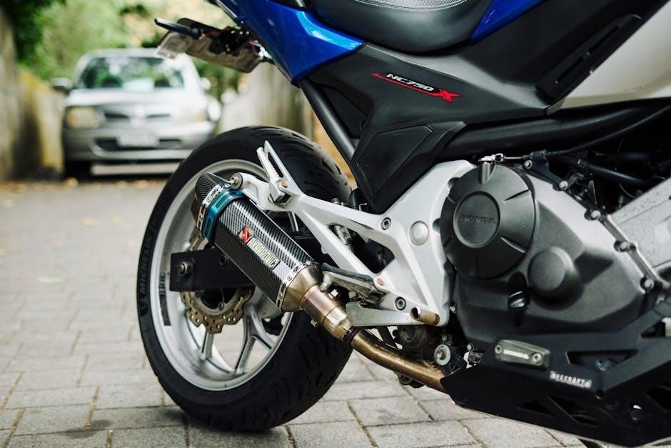
Programmable settings allow you to customize your audio and climate preferences. Refer to the manual for details on connecting external devices or troubleshooting common issues. Proper use of these systems ensures a comfortable and enjoyable driving experience for everyone in the vehicle.

Obtaining the Owners Manual

The 2010 Honda Odyssey Owners Manual can be downloaded for free from Honda’s official website or ordered as a printed copy. Visit Honda’s website, enter your VIN, and follow the instructions to access or request your manual. Original owners can also obtain a free printed manual within the first six months of ownership.

10.1 How to Download a Digital Copy of the Manual

To download a digital copy of the 2010 Honda Odyssey Owners Manual, visit Honda’s official website. Select your vehicle’s model year and enter your Vehicle Identification Number (VIN). Follow the prompts to access the manual in PDF format. This service is free and provides a convenient digital reference for easy access to information.

10.2 Ordering a Printed Copy of the Manual

To order a printed copy of the 2010 Honda Odyssey Owners Manual, visit Honda’s official website and navigate to the owners manual section. Enter your vehicle’s VIN and follow the prompts to request a printed manual. The original owner can obtain a free printed manual within the first six months of ownership. Allow time for shipping and delivery.

Additional Resources for Owners

Honda offers customer support and online communities for Odyssey owners. Visit Honda’s website for contact information, forums, and resources to enhance your ownership experience.

11.1 Honda Customer Support and Contact Information

Honda provides dedicated customer support for 2010 Odyssey owners. Visit Honda’s official website for contact details, including phone numbers, email, and live chat options. Additionally, owners can access resources like FAQs, troubleshooting guides, and service appointment scheduling tools. For personalized assistance, owners can also reach out to local Honda dealerships or customer care representatives directly.

11.2 Online Communities and Forums for Honda Odyssey Owners

Online communities and forums dedicated to Honda Odyssey owners offer valuable resources and support. Platforms like Honda Forums, Odyssey Forums, Reddit, and Facebook groups provide spaces for discussing maintenance, modifications, and troubleshooting. Engaging with these communities can help owners share experiences, find solutions, and stay updated on the latest tips and advice for their vehicles.

This concludes the 2010 Honda Odyssey Owner’s Manual. Regularly referencing this guide ensures optimal performance, safety, and longevity of your vehicle. Happy driving!

12.1 Final Tips for Maximizing Your Vehicle’s Performance

To maximize your 2010 Honda Odyssey’s performance, adhere to the recommended maintenance schedule, monitor fluid levels, and address warning lights promptly. Regular tire pressure checks and proper driving habits enhance fuel efficiency and overall vehicle longevity. Always refer to your owner’s manual for specific guidelines tailored to your Odyssey.

12.2 Importance of Referencing the Manual Regularly

Regularly referencing the 2010 Honda Odyssey Owners Manual ensures safe and optimal vehicle operation. It provides clear guidelines for maintenance, troubleshooting, and understanding advanced features. By following the manual, you can prevent potential issues, enhance performance, and extend the lifespan of your vehicle. Keep it handy for quick access to essential information whenever needed.

e-bike lcd display manual

Welcome to the comprehensive guide for your e-bike LCD display. This manual provides essential information to ensure optimal performance, safety, and ease of use. Read carefully to understand all functions and settings for a seamless riding experience.

Overview of the E-Bike LCD Display

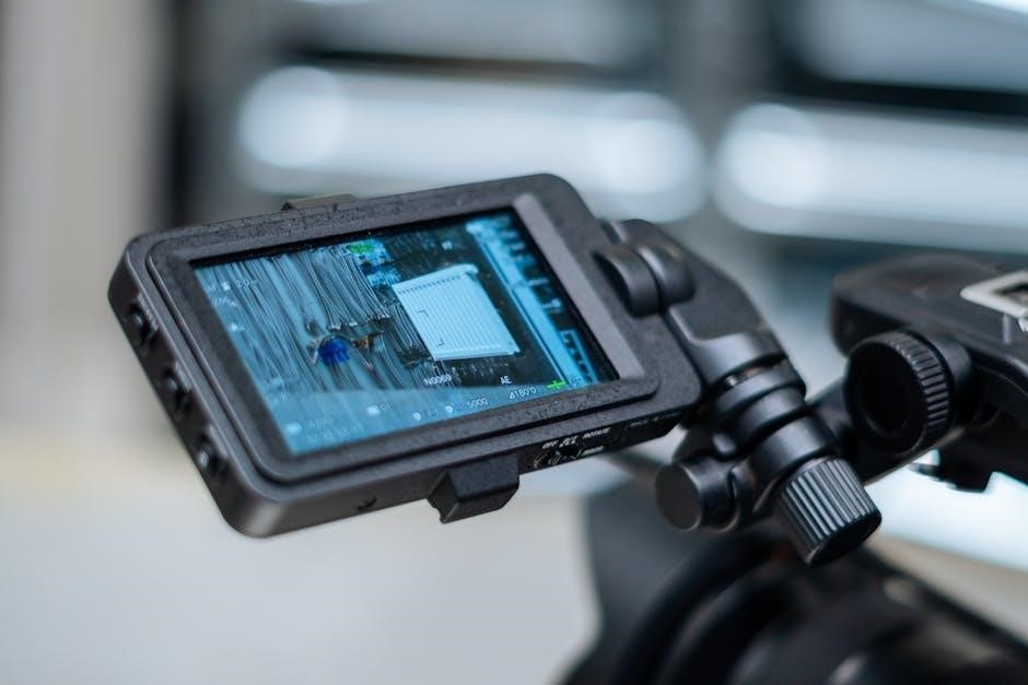
The e-bike LCD display is a intelligent control unit designed to monitor and manage your electric bicycle’s performance. It features a durable, high-hardness acrylic screen, equivalent to tempered glass, ensuring longevity. The display supports multiple voltage options (24V/36V/48V) and operates with low power consumption, making it efficient. It shows real-time data such as speed, battery level, PAS modes, and error codes. Additionally, it offers customizable settings and advanced features like cruise control and adjustable parameters, enhancing your riding experience. This user-friendly interface is essential for both novice and experienced e-bike users.

Importance of Reading the Manual

Reading the e-bike LCD display manual is crucial for understanding its features, settings, and troubleshooting. It ensures safe and optimal use of your e-bike, helping you avoid potential damage to the display or electrical components. The manual provides guidance on navigating modes, customizing parameters, and interpreting error codes. By following the instructions, you can maximize your riding experience, resolve issues efficiently, and maintain the longevity of your LCD display. Proper understanding of the manual also enhances safety and performance while riding.

Technical Specifications of the E-Bike LCD Display

The e-bike LCD display supports 24V/36V/48V power supply, with a rated current of 10mA and maximum current of 30mA. It features a durable, high-hardness acrylic screen.

Voltage and Power Supply Options

The e-bike LCD display is designed to operate efficiently across various voltage levels. It supports 24V, 36V, and 48V power supplies, ensuring compatibility with most e-bike systems. The display’s rated working current is 10mA, with a maximum current of 30mA during peak operations. This flexibility allows the display to function seamlessly with different battery configurations and motor setups. Proper voltage matching ensures optimal performance and prevents potential damage to the system. Always verify your e-bike’s voltage specifications before connecting the display.

Current Ratings and Power Consumption

The LCD display is designed with efficient power consumption in mind. It operates with a rated current of 10mA and a maximum current of 30mA, ensuring minimal battery drain. This low power consumption allows for extended use without significantly affecting your e-bike’s range. The display also features a shutdown leakage current of less than 1µA, further conserving battery life when the system is inactive. These specifications ensure reliable performance while maintaining energy efficiency, making it suitable for long rides and daily commuting.

Display Type and Durability

The LCD display features a high-resolution screen made of imported high-hardness acrylic, offering durability comparable to tempered glass. The ABS shell provides robust protection against impacts and environmental factors. Designed with waterproofing, the display achieves an IP6 rating, ensuring reliability in wet conditions. The screen’s surface is covered with a waterproof film to maintain its performance. The holder is engineered for secure mounting, ensuring stability during rides. These features ensure the display remains clear and functional, even in challenging conditions, providing long-term reliability for your e-bike adventures.

Installation and Setup Guide

Mount the display securely on the handlebar, ensuring proper alignment and tightening. Connect the cables to the e-bike controller, following the manual’s step-by-step instructions for a safe setup.

Physical Installation of the Display

Mount the LCD display on your e-bike’s handlebar using the provided mounting bracket. Ensure the display is aligned correctly and securely tightened to avoid vibration damage. The ABS shell and high-hardness acrylic screen ensure durability. Position the display within clear visibility for safe riding. Tighten all screws firmly to prevent loosening during use. Double-check the installation to confirm the display is level and properly fastened. This ensures optimal performance and longevity of the LCD display. Follow the manual’s diagrams for precise placement and alignment.

Connecting the Display to the E-Bike Controller

Connect the LCD display to the e-bike controller using the provided waterproof connector. Ensure the plug is aligned correctly and fully seated to avoid loose connections. The display is compatible with 24V/36V/48V power supply systems and operates at a rated current of 10mA. Verify the voltage matches your e-bike’s specifications before connecting. Turn off the e-bike’s power before plugging in the display to prevent damage. Secure the connector firmly to ensure reliable communication between the display and controller during operation.

Daily Usage and Functionality

Learn how to operate your e-bike LCD display daily. Use buttons to navigate modes, adjust settings, monitor speed, battery, and assist levels. Press and hold for cruise control effortlessly.

Basic Operations and Button Functions

Mastering basic operations ensures smooth control of your e-bike. The LCD display features buttons for navigating menus, adjusting settings, and monitoring real-time data like speed and battery levels. Press UP or DOWN to cycle through modes, while SET confirms selections. Long-pressing buttons activates features like cruise control or resetting the odometer. The display shows vital information, such as power levels, PAS modes, and error codes, ensuring you stay informed. Familiarize yourself with button functions to optimize your riding experience and maintain control effortlessly.

Navigating Through Display Modes

Navigating the LCD display is intuitive, with buttons allowing easy access to various modes. Press the UP or DOWN buttons to cycle through options like speed, battery level, PAS settings, and odometer. The SET button confirms selections, while long-pressing activates features like cruise control or resetting the odometer. The display shows real-time data, such as power levels, speed, and error codes, ensuring you stay informed. Use the buttons to switch between modes seamlessly and access the information you need for a controlled and enjoyable ride.

Advanced Features of the LCD Display

Cruise control, customizable parameters, and multi-function displays enhance your e-bike experience. Adjust settings and monitor real-time data for a personalized and efficient ride.

Cruise Control and Speed Settings

The LCD display offers advanced cruise control and speed management. Press and hold buttons to activate 6KM/H cruising mode when stopped or switch to real-time speed while riding. Adjust settings for personalized performance, ensuring smooth control. The display shows speed in real-time, updating every five seconds, and features maximum speed memory. Error codes and indicators alert you to system status changes, ensuring safe and efficient operation. Use these features to enhance your riding experience and maintain optimal control over your e-bike’s performance.

Customizable Parameters and Settings

The LCD display allows customization of various parameters to suit your riding preferences. Adjust PAS levels, speed limits, and display settings for a personalized experience. Use the buttons to navigate through menus and modify settings like Eco, Standard, or Power modes. Customize brightness, unit systems, and data display options. The multi-function area lets you adjust parameters quickly. Long presses can reset odometers or toggle features like cruise control. These settings ensure optimal performance and comfort, tailored to your specific needs for an enhanced e-bike experience.

Troubleshooting Common Issues

This section helps resolve common issues like error codes, connectivity problems, and display malfunctions. Follow troubleshooting steps to restore your e-bike’s LCD display functionality effectively.

Understanding Error Codes

Error codes on your e-bike LCD display indicate specific issues. Codes like E01 or E02 often relate to battery or controller communication problems. Refer to the manual’s diagnostic guide to decode each error. Addressing these codes promptly ensures optimal performance and prevents further damage; If unsure, consult the troubleshooting section for detailed solutions. Regularly updating firmware and maintaining proper connections can help minimize errors. Always follow the manufacturer’s instructions for accurate diagnosis and quick resolution.

Resolving Connectivity and Display Problems

To resolve connectivity issues, ensure the display is properly connected to the controller and battery. Restart the system by turning the e-bike off and on. Check for loose wires or corrosion. For display problems, clean the screen with a soft cloth and avoid harsh chemicals. If the display is unresponsive, reset it by pressing and holding the power button for 5 seconds. Addressing these issues promptly ensures smooth operation and prevents further complications. Always handle the display gently to maintain its functionality and longevity.

Maintenance and Care Tips

Regularly clean the LCD screen with a soft cloth and avoid harsh chemicals. Handle with care to prevent scratches. Update firmware periodically and ensure secure connections for optimal performance.

Cleaning and Protecting the Display

Regularly clean the LCD display with a soft, dry cloth to prevent dust buildup. Avoid using harsh chemicals or abrasive materials that may scratch the screen. For stubborn marks, lightly dampen the cloth with water, but ensure no moisture seeps behind the display. Never remove the waterproof protective film, as it ensures the screen’s water resistance. Store the e-bike in a dry, cool place when not in use to extend the display’s lifespan and maintain its clarity and responsiveness.

Updating Firmware and Software

To ensure your e-bike LCD display performs optimally, regular firmware and software updates are essential. Download the latest updates from the manufacturer’s official website. Connect the display to your computer using a USB connector if provided. Follow the on-screen instructions to complete the update process. Never unplug or power off the display during an update, as this may cause irreversible damage. After completion, restart your e-bike to apply the changes. Always verify the update source to avoid unauthorized or malicious software installations.

Safety Precautions and Warnings

Avoid plugging or unplugging the display while the e-bike is powered on. Prevent bumps or impacts to protect the screen. Do not remove the waterproof film, as it may compromise water resistance. Handle the display with care to avoid damage. Follow all manufacturer guidelines for safe operation and storage to ensure longevity and functionality.

Avoiding Damage to the Display

To maintain your e-bike LCD display’s performance and longevity, avoid plugging or unplugging it while the bike is powered on. Prevent bumps or impacts, as they may damage the screen. Do not remove the waterproof film, as this could compromise its water resistance. Handle the display gently to avoid scratches or cracks. Store it in a dry, cool place when not in use. Follow these precautions to ensure your LCD display remains functional and durable for years to come.

Safe Handling and Storage Practices

Handle the LCD display gently to prevent scratches or damage. Avoid exposing it to harsh chemicals, water, or extreme temperatures. Clean the screen with a soft, dry cloth to maintain clarity. When storing, keep the display in a cool, dry place away from direct sunlight and moisture. Ensure the display is powered off and protected with a cover or pouch. Proper storage and handling will extend the life of your e-bike LCD display and ensure optimal performance.

th6220d1028 install manual

The Honeywell TH6220D1028 is a programmable digital thermostat from the FocusPRO series, designed for ease of use and energy efficiency․ It features adaptive intelligent recovery and straightforward installation, making it a reliable choice for home climate control․

1․1 Overview of the Honeywell FocusPRO Series

The Honeywell FocusPRO series offers a range of programmable thermostats designed for simplicity and efficiency․ Known for their user-friendly interface, these thermostats provide precise temperature control and energy-saving features․ The series includes models like the TH6220D1028, which combines advanced functionality with easy installation․ FocusPRO thermostats are ideal for homeowners seeking reliable climate control with minimal complexity․ They feature intuitive controls, adaptive recovery, and compatibility with various HVAC systems, making them a popular choice for modern homes․

1․2 Key Features of the TH6220D1028 Model

The TH6220D1028 model boasts a programmable interface with a backlit display, allowing for easy scheduling and adjustments․ It features adaptive intelligent recovery, ensuring the set temperature is reached on time․ This thermostat supports both heating and cooling systems, with options for manual or auto changeover modes․ Its compatibility with multi-stage HVAC systems enhances performance․ Additionally, it includes field jumper options for auxiliary heat configurations, making it versatile for various setups․ These features make the TH6220D1028 a practical and efficient choice for home climate control․

Accessing the Installation Manual

The Honeywell TH6220D1028 installation manual is readily available for download as a PDF on Honeywell’s official website, ensuring easy access to comprehensive setup instructions and guidelines․

2․1 Downloading the PDF Manual

Visit Honeywell’s official website and navigate to the support section․ Search for the TH6220D1028 model to access the PDF manual․ Ensure compatibility with your device and save the file for offline use․ This manual provides detailed installation steps, system requirements, and troubleshooting tips to ensure a smooth setup process․ Always refer to the latest version for accurate information and safety guidelines․

2․2 Navigating the Manual’s Contents

The TH6220D1028 manual is organized into clear sections, starting with safety precautions and system requirements․ Refer to the table of contents for quick access to installation, wiring diagrams, and configuration steps․ Detailed troubleshooting guides are included to address common issues․ Use the index to locate specific topics, such as adaptive recovery or changeover modes․ Ensure you review all sections relevant to your setup before proceeding with installation or configuration․

System Requirements and Compatibility

The TH6220D1028 is compatible with most HVAC systems, including single-stage heating and cooling․ It requires a 24VAC power supply and supports conventional or heat pump setups, ensuring versatility for various home configurations and energy-efficient performance․

3․1 Checking System Compatibility

Before installation, ensure the TH6220D1028 is compatible with your HVAC system․ Verify that your system operates at 24VAC and supports single-stage heating and cooling․ Check if your system includes a heat pump or emergency heat, as the thermostat supports these configurations․ Review the wiring diagram in the manual to confirm compatibility with your existing setup․ Incompatible systems may lead to improper function or safety hazards, so consulting the manufacturer’s guidelines is crucial for a safe and effective installation․

3․2 Understanding Electrical Requirements

The TH6220D1028 operates on a 24VAC system and requires a common wire (C-wire) for proper functionality․ Ensure your HVAC system meets these voltage specifications to avoid damage or malfunctions․ Review the wiring diagram in the manual to confirm compatibility with your existing electrical setup․ If uncertain, consult a licensed electrician to ensure safe and correct installation․ Proper electrical connections are critical for reliable performance and energy efficiency, so adhering to the manufacturer’s guidelines is essential for a successful setup․

Pre-Installation Steps

Before installation, ensure the power is turned off at the circuit breaker․ Gather all necessary tools and materials, and prepare the installation location by cleaning and leveling the surface․

4․1 Gathering Necessary Tools and Materials

To install the Honeywell TH6220D1028 thermostat, gather essential tools: a screwdriver, wire strippers, and a level․ Ensure you have the thermostat unit, wallplate, screws, and jumper wires․ Verify all components are included in the packaging․ Additionally, prepare a pencil for marking wire connections and a voltage tester for safety checks․ Having these materials ready ensures a smooth and efficient installation process, minimizing downtime and potential errors during setup․

4․2 Preparing the Installation Location

Before installation, turn off power to the HVAC system at the circuit breaker; Locate the ideal spot for the thermostat, typically 5 feet above the floor․ Remove the old thermostat and inspect the wires for damage․ Clean the area to ensure a secure mount․ If necessary, label the wires for easy identification․ Ensure the wall is level and sturdy to support the thermostat․ Proper preparation ensures a safe and accurate installation, preventing potential issues with wiring or placement․

Installation Process

Mount the thermostat about 5 feet above the floor, ensuring level placement․ Connect wires according to the manual, then secure the thermostat to the wallplate․ Turn on power and test functionality to ensure proper operation․

5․1 Mounting the Thermostat

Mount the thermostat about 5 feet above the floor, away from direct sunlight and drafts․ Remove the existing thermostat and carefully handle the wires․ Attach the wallplate to the wall, ensuring it is level․ Mount the thermostat onto the wallplate, plugging the wires into their corresponding terminals․ Secure the thermostat firmly to the wallplate․ Refer to the manual for specific mounting hardware and alignment instructions to ensure proper installation and functionality․

5․2 Connecting the Wires

Connect the wires carefully, following the manual’s wiring diagram․ Ensure the power is off before starting․ Remove the wallplate and connect the wires to the corresponding terminals on the thermostat․ Match the wires to their correct terminals, such as R, W, Y, G, and C․ Secure the connections firmly to avoid loose wires․ Double-check the wiring to ensure compatibility with your system․ Refer to the manual for specific wiring instructions and guidelines to ensure safe and proper installation․ Proper wiring is essential for the thermostat to function correctly․ Always follow safety precautions․

Post-Installation Configuration

Set up the thermostat’s schedule and test the system to ensure proper functionality․ Adjust settings as needed to optimize performance and energy efficiency․

6․1 Setting Up the Thermostat’s Schedule

The TH6220D1028 allows you to program custom schedules for heating and cooling․ Use the built-in guide to set temperature preferences for different days and times․ Select “Set Schedule” and choose from pre-set templates or create a custom plan; Ensure the adaptive intelligent recovery feature is enabled to reach programmed temperatures on time․ After setting, review and test the schedule to confirm proper operation․ Adjust settings as needed to optimize comfort and energy savings․

6․2 Testing the System

After configuration, test the system to ensure proper operation․ Run a test cycle by selecting “Test Run” in the menu․ Check if the thermostat activates heating or cooling as scheduled․ Verify adaptive intelligent recovery by setting a target temperature and observing if it reaches the desired level on time․ Switch between manual and auto modes to confirm smooth transitions․ Refer to the manual for detailed testing steps․ Ensure all features function correctly before finalizing the setup․

Safety Precautions

Always follow the manufacturer’s guidelines to ensure safe installation and operation․ Turn off power before starting work to avoid electrical hazards․ Handle components carefully to prevent damage․

7․1 Following Manufacturer’s Guidelines

Adhering to Honeywell’s instructions is crucial for safe and proper installation․ The TH6220D1028 manual provides detailed steps to avoid hazards and ensure system compatibility․ Reading the manual thoroughly before starting ensures compliance with safety standards and prevents potential risks․ Always follow the recommended procedures for wiring, mounting, and configuring the thermostat to maintain reliability and performance․ Ignoring guidelines can lead to malfunctions or safety issues, emphasizing the importance of careful adherence to manufacturer recommendations․

7․2 Ensuring Proper Electrical Safety

Electrical safety is paramount when installing the TH6220D1028․ Always switch off power at the circuit breaker before starting work․ Verify voltage compatibility to prevent damage․ Use a voltage tester to confirm the absence of live wires․ Ensure all connections are secure and avoid overloading circuits․ Install the thermostat on a GFCI-protected outlet if required․ Never bypass safety features or ground wires, as this can lead to hazards․ Follow the manual’s electrical guidelines strictly to maintain safety and system integrity․

The TH6220D1028 offers advanced features like adaptive intelligent recovery, ensuring programmed temperatures are met on time, and manual/auto changeover modes for flexible system control․

Advanced Features

8․1 Adaptive Intelligent Recovery

Adaptive Intelligent Recovery ensures the thermostat reaches the programmed temperature by the scheduled time, optimizing performance and energy use․ It learns the system’s behavior to pre-activate heating or cooling, maintaining comfort without unnecessary energy consumption․ This feature is especially beneficial for maintaining consistent temperatures during peak times, enhancing overall efficiency and user satisfaction․ It operates seamlessly in the background, requiring no manual adjustments once programmed․

8․2 Manual vs․ Auto Changeover Modes

The TH6220D1028 offers Manual and Auto changeover modes․ Manual mode requires the user to switch between heating and cooling modes, while Auto mode automatically transitions based on the programmed temperature․ Auto mode enhances efficiency by optimizing system operation, reducing manual adjustments․ Manual mode provides flexibility for specific scenarios, but may require more user intervention․ Both modes ensure reliable temperature control, catering to different user preferences and system requirements․

Troubleshooting Common Issues

Identify common issues like wiring problems or display malfunctions․ Check connections, ensure proper installation, and refer to the manual for solutions․ Contact Honeywell support if unresolved․

9․1 Identifying and Resolving Wiring Issues

Wiring issues are common during installation․ Check for loose connections, incorrect terminal assignments, or short circuits․ Ensure power is off before inspecting wires․ Verify compatibility with your HVAC system․ Consult the manual for proper wire color-coding and connections․ If issues persist, refer to troubleshooting guides or contact a professional․ Always follow safety precautions to avoid electrical hazards or system damage․

9․2 Addressing Display or Functional Problems

If the display is blank, unresponsive, or showing incorrect temperatures, check the power supply and ensure proper wiring․ Restart the thermostat by turning it off and on․ Verify battery levels if applicable․ For functional issues, review the schedule settings and ensure correct mode selection (Heat/Cool/Auto)․ If problems persist, consult the manual or contact Honeywell support․ Always follow the manufacturer’s troubleshooting guidelines to resolve issues effectively and safely․

Environmental Disposal Instructions

Always dispose of the Honeywell TH6220D1028 thermostat responsibly․ Contact local waste management for recycling guidelines, ensuring eco-friendly disposal and compliance with environmental regulations․ Proper disposal helps protect the environment․

10․1 Proper Recycling of Old Thermostats

For proper recycling of old thermostats like the Honeywell TH6220D1028, contact your local waste management authority for specific guidelines․ Many communities offer designated facilities for electronics and hazardous waste․ Old thermostats may contain mercury or other harmful materials, requiring special handling to prevent environmental contamination․ Proper recycling ensures safe disposal and helps conserve natural resources․ Always follow local regulations and consider participating in manufacturer-sponsored recycling programs if available․ This responsible approach supports environmental sustainability and reduces waste․

10․2 Local Waste Management Guidelines

Consult your local waste management authority for specific guidelines on disposing of thermostats like the TH6220D1028․ Many communities offer designated collection events or facilities for electronics and hazardous waste․ Check for nearby drop-off locations that accept thermostats, especially those containing mercury or other regulated materials․ Proper disposal ensures compliance with environmental regulations and prevents harmful substances from entering landfills․ Contact your local government or waste management provider for detailed instructions tailored to your area․

biddeford electric blanket instruction manual

The Biddeford Electric Blanket offers exceptional comfort and safety, featuring dual controllers for larger sizes and multiple heat settings. Designed for ease of use, it provides soothing warmth and relaxation, ideal for cold nights. Available in various styles, including heated mattress pads and throws, it ensures a cozy sleeping experience while prioritizing user safety and energy efficiency.

1.1 Overview of the Product

The Biddeford Electric Blanket is a versatile, user-friendly heating solution designed for comfort and safety. Available in styles like heated mattress pads, throws, and blankets, it offers dual controllers for larger sizes and multiple heat settings. Ideal for cold nights, it provides soothing warmth while ensuring energy efficiency. The product comes with a desktop digital controller, such as the TC16BO, and is supported by a comprehensive user manual for easy operation and maintenance.

1.2 Key Features and Benefits

The Biddeford Electric Blanket boasts key features such as dual controllers for larger sizes. It offers 10 adjustable warmth settings. The desktop digital controller ensures easy operation, providing consistent heat distribution. Its design prioritizes safety, with automatic shut-off and secure wiring. The blanket enhances sleep quality, soothes muscles, and alleviates aches. It is energy-efficient and comes with a user-friendly manual. Available in various sizes. It is designed for optimal comfort and convenience.

Safety Instructions

Always follow safety guidelines to prevent accidents. Avoid submerging the blanket in water and keep it away from pets. Use only the supplied controller and ensure proper placement. Never tuck the blanket or cord into furniture, and inspect for damage before use. Adhere to all warnings to ensure safe operation and longevity.

2.1 General Safety Guidelines

Always follow safety guidelines to prevent accidents. Avoid submerging the blanket in water and keep it away from pets. Use only the supplied controller and ensure proper placement. Never tuck the blanket or cord into furniture, and inspect for damage before use. Adhere to all warnings to ensure safe operation and longevity.

2.2 Important Safety Precautions

Prevent burns by avoiding overheating. Never use the blanket if damaged or wet. Keep the control unit dry and avoid folding the blanket while in use. Ensure all portions of the blanket and cord remain visible. Follow instructions carefully to prevent electrical hazards and maintain safety. Regular inspections and proper storage are essential for optimal performance and user protection.

Installation and Setup

Unpack the blanket carefully, ensuring no damage. Plug it into a working outlet and power it on. Set up the controller for dual-sided heating in larger models.

3.1 Unpacking and Initial Inspection

When unpacking your Biddeford Electric Blanket, carefully remove all packaging materials. Inspect the blanket and controller for any visible damage or defects. Ensure all components, including the power cord and dual controllers for larger sizes, are included. Check for any signs of wear or damage to the heating elements and wiring. If any issues are found, do not use the blanket and contact customer support immediately.

3.2 Plugging in and Powering On

Plug the Biddeford Electric Blanket into a working 120V electrical outlet. Ensure the outlet is GFCI-protected for safety. For larger sizes, connect both dual controllers to their respective sides of the blanket. Make sure the controller cord is securely attached to the blanket. Avoid using extension cords. Once plugged in, the digital controller will light up, indicating it is ready for operation. Keep the blanket flat and avoid tucking it into furniture while in use.

3.3 Controller Features and Functions

The Biddeford Electric Blanket controller offers a digital display with easy-to-use buttons for adjusting heat settings. It features 10 selectable heat levels, a timer function, and indicators for heat and timer status. The controller is designed for dual-sided heating in larger blanket sizes, ensuring even warmth distribution. Use the buttons to increase or decrease heat, set the timer, or turn the blanket off. LED indicators provide clear feedback on the current settings.

Operating the Electric Blanket

Operating the Biddeford Electric Blanket is straightforward. Use the controller to adjust heat settings, set the timer, and enjoy safe, even warmth for ultimate comfort.

4.1 Turning On the Blanket

Turning on the Biddeford Electric Blanket is simple and safe. First, ensure it is properly plugged into a working outlet. Use the controller to press the power button, then select your desired heat setting. The digital display will confirm your selection. Always keep the blanket on top of bedding and avoid tucking it into furniture. Ensure the cord is visible and unobstructed to maintain safety. The blanket is designed for energy-efficient operation and enhanced sleep quality.

4.2 Adjusting Heat Settings

Adjusting the heat settings on your Biddeford Electric Blanket is straightforward. Use the digital controller to select from 10 different heat levels. Press the “+” or “-” buttons to increase or decrease the temperature. The controller will display the chosen setting, and the blanket will adjust accordingly. For optimal comfort, start with a lower setting and gradually increase as needed. Always ensure the blanket is on a flat surface and not folded during operation.

4.3 Turning Off the Blanket

To turn off the Biddeford Electric Blanket, press the power button on the controller until the display turns off. Ensure the blanket has cooled down before handling. For complete shutdown, unplug the power cord from the outlet. Always follow safety guidelines to avoid damage or hazards. Never leave the blanket unattended while in use, and store it properly when not in operation to maintain its functionality and longevity.

4.4 Using Dual Controllers for Larger Sizes

Larger Biddeford Electric Blankets, such as King and Queen sizes, come with dual controllers for independent heat adjustment on both sides. Each controller operates separately, allowing users to customize their comfort. With 10 warming settings, you can tailor the heat to your preference. For synchronized use, ensure both controllers are set to the same mode. Always keep the blanket and cords visible to ensure safe operation and optimal performance.

Maintenance and Care

Regularly wash the blanket in a gentle cycle with mild detergent. Avoid machine drying; air dry instead. Store in a cool, dry place when not in use. Never use harsh chemicals or bleach, as they may damage the heating elements. Proper care ensures longevity and safe operation of your Biddeford Electric Blanket.

5.1 Cleaning and Washing Instructions

To clean your Biddeford Electric Blanket, machine wash it on a gentle cycle using mild detergent. Avoid using bleach or harsh chemicals, as they may damage the heating elements. Do not machine dry; instead, air dry the blanket flat or hang it to prevent shrinkage. For hand washing, use cold water and gentle agitation. Always check the care label for specific instructions. Proper cleaning ensures the blanket remains safe and functional.

5.2 Storage and Handling Tips

Store your Biddeford Electric Blanket in a cool, dry place when not in use. Avoid folding or creasing the blanket, as this can damage the heating elements. Keep the controller and cord tidy, ensuring they are not tangled or pinched. Do not submerge electrical components in water. For extended storage, place the blanket in its original packaging or a breathable fabric bag. Always handle the blanket gently to maintain its quality and functionality.

Troubleshooting Common Issues

Check power connections and ensure the outlet is working. Reset the controller or unplug and replug the blanket. Inspect for visible damage or loose wires.

6.1 Diagnosing Common Problems

Common issues include the blanket not heating, uneven warmth, or controller malfunctions. Check if the blanket is properly plugged in and the outlet is functional. Ensure the controller is working and settings are correct. Inspect for visible damage or loose connections. Reset the controller by unplugging and replugging it. If issues persist, refer to the user manual or contact customer support for further assistance.

6.2 Resolving Heating Issues

If the blanket isn’t heating, first ensure it’s properly plugged in and the outlet is working. Check the controller settings and confirm it’s turned on. For uneven heat, smooth out the blanket to ensure even distribution. If the issue persists, reset the controller by unplugging it for 30 seconds and replugging it. Avoid using extension cords, as they may reduce power supply. Refer to the manual for detailed troubleshooting steps.

6.3 Controller Malfunction Solutions

If the controller isn’t functioning, first ensure it’s securely plugged into a working outlet. Reset the controller by unplugging it for 30 seconds and replugging it. Check the controller settings to confirm they’re correctly configured. Avoid using extension cords, as they may disrupt power supply. If issues persist, contact Biddeford’s customer support for further assistance or potential replacement. Always prioritize safety by discontinuing use until the issue is resolved.

Warranty and Customer Support

Biddeford Electric Blankets come with a 5-year warranty covering manufacturing defects. For assistance, contact customer service at 800.789.6441 or visit their website for support and solutions.

7.1 Understanding the Warranty

Biddeford Electric Blankets are backed by a 5-year limited warranty covering defects in materials and workmanship. The warranty starts from the purchase date and applies to original buyers only. It does not cover damage from misuse, improper care, or normal wear and tear. For warranty claims, contact customer service with proof of purchase and a detailed description of the issue. Repairs or replacements are handled at the manufacturer’s discretion.

7.2 Contacting Customer Service

For assistance with your Biddeford Electric Blanket, contact customer service at 800.789.6441 or visit their official website. Support is available to address warranty claims, troubleshooting, and general inquiries. Have your product model and purchase details ready for efficient service. Biddeford’s customer support team is committed to resolving issues promptly and ensuring customer satisfaction.

Additional Resources

Visit the official Biddeford website for user manuals, troubleshooting guides, and FAQs. Additional resources include downloadable PDF manuals and customer support contact information for assistance.

8.1 Downloading the User Manual

Visit the official Biddeford website to download the user manual for your electric blanket. Search for your specific model, such as the TC16BO, and access the PDF guide. The manual includes detailed instructions for operation, safety, and troubleshooting; Ensure you download the correct version for your product by verifying the model number. Additional resources, like FAQs and troubleshooting guides, are also available for a comprehensive user experience.

8.2 Visiting the Manufacturer’s Website

Visit the official Biddeford website for comprehensive resources, including product details, user manuals, and customer support. Explore FAQs, troubleshooting guides, and warranty information to enhance your experience. The website offers direct access to downloadable manuals and provides contact details for assistance. Regular updates and new product releases are also featured, ensuring you stay informed about your Biddeford Electric Blanket and related accessories.

liftmaster 84501 manual

The LiftMaster 84501 is a smart Wi-Fi-enabled garage door opener‚ offering ultra-quiet belt drive operation‚ integrated LED lighting‚ and seamless myQ app integration for remote monitoring and control.

Safety Precautions and Warnings

Before installing or operating the LiftMaster 84501‚ carefully read and follow all safety instructions to avoid potential hazards. Ensure the garage door is properly balanced and lubricated‚ as an unbalanced door can cause injury or damage. Never install the opener on a door that is not functioning correctly. Avoid modifying the opener or its components‚ as this may void the warranty and create safety risks. Always keep the emergency release handle clear of obstructions. Be cautious when working with electrical components‚ and ensure all connections are secure. Properly supervise children and pets near the garage door. Failure to adhere to these precautions may result in serious injury or damage. Refer to the manual for detailed safety guidelines and warnings.

Installation Guide

Install the LiftMaster 84501 by aligning the rail with the garage door‚ securing the mounting hardware‚ and connecting the power source. Follow the step-by-step guide carefully.

3.1. Pre-Installation Checklist

  • Ensure you have all necessary tools and hardware included in the package.
  • Read and understand the safety materials and installation instructions thoroughly.
  • Verify the garage door is properly balanced and lubricated before installation.
  • Check the ceiling clearance and ensure the area is clear of obstacles.
  • Confirm the power source is available and meets the opener’s requirements.
  • Review the rail alignment and mounting points for proper installation.
  • Ensure the opener is compatible with your garage door size and type.

These steps ensure a smooth and safe installation process for your LiftMaster 84501 garage door opener.

3.2. Step-by-Step Installation Process

  1. Assemble the rail by attaching the motor unit and trolley according to the manual’s instructions.
  2. Secure the motor to the ceiling using the provided mounting hardware.
  3. Attach the trolley to the garage door and align it with the motor rail.
  4. Install the rail system‚ ensuring proper alignment and level placement.
  5. Attach the belt or chain to the motor and trolley‚ following the manufacturer’s tension guidelines.
  6. Hang the opener and connect all necessary wires and sensors.

Always follow the LiftMaster 84501 manual for precise instructions and safety precautions during installation.

3.3. Post-Installation Setup

After installation‚ test the door to ensure smooth operation and proper alignment.

  • Program the remote controls by pressing the learn button and following the manual’s instructions.
  • Set up safety sensors to ensure the door stops if an obstacle is detected.
  • Connect to the myQ app for smart features‚ enabling remote monitoring and control.

Refer to the LiftMaster 84501 manual for detailed steps to complete the setup and ensure everything functions correctly.

Features and Specifications

The LiftMaster 84501 features a belt drive for ultra-quiet operation‚ an integrated LED lighting system for enhanced visibility‚ and compatibility with the myQ app for smart control.

4.1. Drive Type and Motor

The LiftMaster 84501 utilizes a reliable belt drive system‚ ensuring ultra-quiet and smooth operation. This design minimizes noise and vibration‚ making it ideal for households where noise can be a concern. The motor is high-torque‚ providing consistent performance and durability. It also features a soft start and stop mechanism‚ which reduces wear and tear on the garage door and opener. The belt drive is maintenance-free‚ eliminating the need for regular lubrication required with chain drives. This combination of power and silence makes the LiftMaster 84501 a top choice for modern homes seeking both functionality and comfort.

4.2. Lighting System

The LiftMaster 84501 is equipped with an integrated LED lighting system‚ providing 1‚500 lumens of bright‚ energy-efficient illumination. This feature enhances visibility in the garage‚ ensuring safety and convenience. The LED light is long-lasting and requires minimal maintenance‚ reducing the need for frequent bulb replacements. Additionally‚ the lighting system is motion-activated in certain settings‚ turning on automatically when movement is detected. This not only improves security but also adds a layer of practicality for nighttime use. The LED light ensures optimal brightness without excessive energy consumption‚ making it an eco-friendly and reliable choice for garage lighting needs. Its seamless integration with the opener further highlights the product’s focus on innovation and user convenience.

4.3. myQ Technology

The LiftMaster 84501 features advanced myQ technology‚ enabling seamless integration with the myQ app. This allows users to monitor and control their garage door remotely via smartphone or tablet. With real-time notifications‚ users receive alerts when the door is opened‚ closed‚ or left open. The app also supports voice commands through platforms like Apple HomeKit and Google Assistant‚ enhancing convenience. Additionally‚ myQ ensures compatibility with various smart home systems‚ allowing for a fully integrated smart home experience. The technology is designed for easy setup and operation‚ providing peace of mind and added security with its robust remote monitoring capabilities. This feature is a standout aspect of the LiftMaster 84501‚ making it a top choice for modern homeowners seeking smart solutions.

Troubleshooting Common Issues

Common issues with the LiftMaster 84501 include the garage door not opening or closing properly‚ remote malfunction‚ or LED light flickering. First‚ ensure the door is properly aligned and balanced. Check the power supply and battery backup for connectivity issues. For remote problems‚ reprogram the remote or replace the battery. If the LED light flickers‚ inspect for loose connections or damaged bulbs. Consult the manual for detailed troubleshooting steps. Regularly lubricate moving parts to prevent friction-related issues. If problems persist‚ reset the system by disconnecting power and reconnecting it. For unresolved issues‚ contact LiftMaster support for assistance. This section helps users quickly identify and resolve common issues‚ ensuring smooth operation and optimal performance. Always refer to the manual for specific guidance.

Maintenance Tips for Optimal Performance

Regular maintenance is essential to ensure the LiftMaster 84501 operates smoothly. Lubricate moving parts annually to reduce friction and wear. Clean the garage door tracks and rollers to prevent debris buildup. Inspect the belt drive for signs of wear or damage and replace it if necessary. Check the LED light for proper function and replace bulbs as needed. Verify the garage door balance and alignment to avoid unnecessary strain on the motor. Test the safety sensors monthly to ensure they function correctly. Update the myQ app and firmware to maintain compatibility and security. By following these tips‚ you can extend the lifespan of your opener and ensure reliable performance. Refer to the manual for detailed maintenance instructions.

Compatible Models and Accessories

The LiftMaster 84501 is part of a series that includes models like the 84602‚ 87504‚ 87504-267‚ and 87802‚ ensuring compatibility and shared features. Accessories include the myQ app for smart integration‚ additional remotes‚ and LED lighting upgrades. Safety sensors and belt drive components are also available‚ enhancing functionality and security. These accessories ensure seamless operation and integration with other smart home systems‚ making the LiftMaster 84501 a versatile choice for modern garage solutions.

Advanced Features and Smart Integration

The LiftMaster 84501 boasts advanced features like a belt drive system for ultra-quiet operation and an integrated LED lighting system for enhanced visibility. The myQ technology allows users to monitor and control their garage door remotely via the myQ app‚ ensuring convenience and peace of mind. This smart integration enables features such as real-time notifications and voice control through platforms like Amazon Alexa and Google Assistant. With robust encryption‚ the myQ system provides secure communication between the opener and the app‚ safeguarding against unauthorized access. These cutting-edge features make the LiftMaster 84501 a modern and efficient solution for smart garage door management.

The LiftMaster 84501 is a cutting-edge‚ Wi-Fi-enabled garage door opener that combines advanced features like a belt drive system‚ LED lighting‚ and smart app integration for seamless control. Its ultra-quiet operation and robust security make it a top choice for modern homeowners. For further assistance‚ the LiftMaster 84501 manual is available as a free PDF download‚ providing detailed installation‚ troubleshooting‚ and maintenance guides. Additional resources‚ including user guides and specs‚ can be found on platforms like Manuals.net and the official LiftMaster website. These resources ensure optimal performance and ease of use for this innovative garage door opener.

craftsman snow blower instruction manual

Welcome to the Craftsman Snow Blower Instruction Manual, your comprehensive guide to understanding and maintaining your equipment․ This manual provides essential information for safe operation, assembly, troubleshooting, and maintenance to ensure optimal performance and longevity of your snow blower․

Designed to help you master your Craftsman Snow Blower, this manual covers everything from initial setup to advanced care tips․ Follow the instructions carefully to maximize efficiency and safety while operating your machine․

Whether you’re a first-time user or a seasoned operator, this guide will empower you with the knowledge needed to handle your snow blower confidently․ Let’s get started!

1․1 Importance of Reading the Manual

Reading the Craftsman Snow Blower Instruction Manual is essential for safe and effective operation․ It provides critical safety guidelines, step-by-step assembly instructions, and maintenance tips to ensure your snow blower performs optimally․ The manual also includes troubleshooting advice to address common issues, helping you avoid costly repairs․ By following the instructions, you can extend the lifespan of your equipment and ensure compliance with warranty terms․ Always prioritize safety and efficiency by thoroughly reviewing the manual before use․

1․2 Understanding the Structure of the Manual

The Craftsman Snow Blower Instruction Manual is organized into clear sections for easy navigation․ It begins with an introduction, followed by safety precautions, assembly instructions, operating guidelines, maintenance tips, and troubleshooting advice․ Each section is designed to address specific aspects of the snow blower, ensuring users can quickly locate relevant information․ The manual also includes detailed diagrams and part lists, making it a comprehensive resource for both novice and experienced operators․ This structured approach ensures a seamless user experience․

Safety Precautions and Guidelines

Always wear protective gear and ensure the area is clear of obstacles․ Avoid operating in unsafe conditions and never leave the snow blower unattended․ Follow all instructions carefully to ensure safe and effective use․

2․1 General Safety Rules

Always wear protective gear, including gloves and eye protection, when operating the snow blower․ Ensure the area is clear of obstacles and bystanders․ Never leave the machine unattended while running․ Keep children and pets at a safe distance․ Avoid operating the snow blower in extreme weather conditions or on uneven terrain․ Regularly inspect the machine for wear and tear, and replace damaged parts with genuine OEM components to maintain safety and performance․ Follow all safety guidelines outlined in the manual to prevent accidents and ensure smooth operation․

2․2 Specific Safety Warnings for Snow Blowers

  • Never operate the snow blower in enclosed spaces, as this can lead to carbon monoxide buildup․
  • Avoid using the machine in extreme weather conditions or on icy surfaces․
  • Do not touch hot surfaces, such as the engine or chute, during or after operation․
  • Keep hands and feet away from moving parts to prevent injury․
  • Regularly inspect shave plates and skid shoes for wear and replace them with genuine OEM parts if damaged․
  • Never modify the snow blower or use unauthorized attachments․
  • Always operate the machine in well-ventilated areas and follow all safety guidelines to ensure safe and effective use․

Assembly and Installation Instructions

Begin with unpacking and inventorying all parts; Follow the step-by-step assembly guide in the manual․ Ensure all bolts and components are securely tightened for safe operation․

3․1 Unpacking and Inventory of Parts

Start by carefully unpacking your Craftsman Snow Blower and verifying all components against the provided parts list․ Check for any damage or missing items․ Organize the parts to ensure easy access during assembly․ Refer to the manual for a detailed inventory guide and instructions on handling delicate components․ This step ensures a smooth assembly process and prevents issues later․ Always use original equipment manufacturer (OEM) parts for optimal performance and safety․

3․2 Step-by-Step Assembly Process

Begin by following the manual’s instructions to assemble your Craftsman Snow Blower․ Attach the handlebars securely, ensuring all bolts are tightened properly․ Next, install the auger and impeller, aligning them correctly for smooth operation․ Connect the chute and deflector, making sure they move freely․ Finally, attach any additional accessories like drift cutters or skid shoes․ Double-check all connections and test the machine on a flat surface to ensure everything functions as expected․ Refer to the manual’s diagrams for clarity and precision․

Operating the Snow Blower

Start the engine according to the manual’s instructions․ Use the throttle to adjust speed and direct the chute for optimal snow dispersion․ Always maintain a safe distance from people and obstacles while operating the machine․ Ensure proper footing and avoid overreaching to maintain control․ Refer to the manual for specific operating tips and safety guidelines․

4․1 Starting the Engine

Before starting the engine, ensure the snow blower is on level ground and the area is clear․ Check the oil level and fill if necessary․ Prime the engine by pulling the primer bulb 2-3 times․ Move the choke to the “start” position and pull the starter cord firmly until the engine ignites․ Once running, gradually move the choke to the “run” position․ Allow the engine to warm up briefly before beginning operation․

4․2 Adjusting Settings for Optimal Performance

Adjust the skid shoes to maintain proper ground clearance, ensuring even snow removal․ Direct the chute to the desired angle and distance for efficient snow discharge․ Use the deflector to control the height of the snow stream․ For varying snow conditions, modify the auger speed and engine throttle to match the load․ Regularly check and adjust these settings to maintain peak performance and prevent unnecessary wear on the machine․

Maintenance and Storage Tips

Regularly clean the snow blower and lubricate moving parts to prevent rust․ Check for worn components and replace them as needed․ Store in a dry, protected area during off-season to maintain performance and longevity․

5․1 Regular Maintenance Checks

Perform routine inspections to ensure your Craftsman Snow Blower operates efficiently․ Check the oil level before each use and top it off as needed․ Inspect the auger and blades for wear or damage, replacing them with genuine OEM parts if necessary․ Lubricate moving components like the chute and impeller to prevent rust and friction․ Regularly clean the machine to remove dirt and debris, ensuring optimal performance and extending its lifespan․ Schedule professional servicing annually to address complex issues early․

Store your Craftsman Snow Blower in a dry, protected area away from direct sunlight and moisture․ Drain the fuel tank or stabilize the fuel with a conditioner to prevent degradation․ Clean the machine thoroughly, removing dirt and debris․ Apply rust-inhibiting oil to metal parts and cover the unit to shield it from dust․ Store the snow blower upright to prevent oil leakage and ensure all components remain functional for the next season․

Troubleshooting Common Issues

5․2 Proper Storage Techniques

Store your Craftsman Snow Blower in a dry, well-ventilated area, away from direct sunlight and moisture․ Clean the machine thoroughly, removing dirt and debris․ Drain the fuel tank or use a fuel stabilizer to prevent degradation․ Apply rust-inhibiting oil to metal parts and cover the unit to protect it from dust․ Ensure all components are secure and store the snow blower upright to prevent oil leakage and maintain functionality for the next season․

6․1 Identifying and Solving Operational Problems

Common issues with the Craftsman Snow Blower include engine failure to start, improper snow discharge, and reduced performance․ Check the spark plug for wear and ensure the oil level is adequate․ Verify fuel quality and proper fuel flow․ Inspect the auger and impeller for blockages or damage․ Ensure all belts and cables are securely connected․ Refer to the manual for specific troubleshooting steps and always use OEM parts for repairs to maintain functionality and safety․

6․2 When to Contact Professional Service

If issues persist after troubleshooting, or if complex mechanical problems arise, contact a certified Craftsman service technician․ Seek professional help for major repairs, such as engine overhauls or transmission issues, to ensure safety and maintain warranty coverage․ Additionally, consult a professional if you lack expertise in advanced repairs or if critical components like the auger or impeller require specialized attention to prevent further damage and ensure optimal performance․

Understanding Parts and Accessories

Familiarize yourself with key components like the auger, impeller, and shave plates․ Genuine Craftsman accessories, such as spark plugs and belts, ensure optimal performance and longevity of your snow blower․

7;1 Overview of Key Components

Understanding your Craftsman Snow Blower begins with identifying its essential parts․ The auger collects snow, while the impeller propels it through the chute․ Other critical components include the shave plate, which scrapes the ground, and skid shoes, which adjust clearing height․ Regularly inspect these parts for wear and replace them with genuine OEM parts to maintain performance and safety․ Refer to your parts manual for detailed diagrams and specifications․

7․2 Recommended OEM Parts and Accessories

For optimal performance and longevity, use genuine OEM parts specifically designed for your Craftsman Snow Blower․ Key replacements include shave plates and skid shoes, which prevent ground damage․ Regularly update belts, spark plugs, and auger kits to maintain efficiency․ Always refer to your parts manual for compatibility and ordering details․ Genuine accessories, like drift cutters and remote chute controllers, enhance functionality․ Ensure safety and performance by avoiding non-OEM alternatives․

Warranty and Service Information

Your Craftsman Snow Blower is backed by a comprehensive warranty covering defects in materials and workmanship․ For service, contact authorized dealers or schedule repairs through the manufacturer’s support network․

8․1 Understanding the Warranty Coverage

Your Craftsman Snow Blower is protected by a warranty that covers manufacturing defects for up to two years from the purchase date․ This includes repairs or replacements of faulty parts and labor costs when serviced by authorized professionals․ Proper maintenance, as outlined in the manual, is essential to uphold warranty validity․ For detailed terms, refer to the warranty section in your manual or contact customer support․

8․2 Scheduling Service and Repairs

For scheduling service or repairs, contact authorized Craftsman service centers or use the online portal to book an appointment․ Ensure you provide your model number and a detailed description of the issue․ Authorized technicians will handle diagnostics and repairs, ensuring compliance with warranty terms․ Regular maintenance and timely repairs can prevent major breakdowns and extend the life of your snow blower․

Environmental and Safety Compliance

Adhere to environmental standards by using eco-friendly fuels and proper disposal methods․ Always follow safety guidelines to minimize risks and ensure responsible operation of your snow blower․

9․1 Eco-Friendly Operation Tips

Optimize your Craftsman Snow Blower’s environmental impact by using the correct fuel type and checking oil levels to prevent leaks․ Maintain proper tire pressure to reduce fuel consumption․ Avoid idling the engine unnecessarily and operate at lower RPMs when possible․ Clear snow in passes rather than attempting to remove deep snow in one go to minimize energy use․ Regularly sharpen the auger and keep the chute clear to ensure efficient operation․ Dispose of waste like oil and filters responsibly․

9․2 Disposal and Recycling Guidelines

Properly dispose of your Craftsman Snow Blower by recycling or donating usable parts․ Remove batteries, oil, and hazardous materials, following local regulations․ Check with recycling centers for acceptable items like metals and plastics․ Donate working components to repair shops or charities․ Ensure environmentally responsible disposal to minimize waste․ Consult local guidelines for detailed instructions and consider consulting the manual or OEM for specific recommendations․

Downloading and Accessing Manuals Online

Easily access Craftsman Snow Blower manuals online by visiting the official website or authorized portals․ Enter your model number to download the correct manual instantly for free․

Explore additional online resources for troubleshooting, maintenance tips, and user guides to enhance your experience with the Craftsman Snow Blower․

10․1 Finding the Correct Manual for Your Model

To find the correct manual for your Craftsman Snow Blower, visit the official website or authorized portals․ Enter your model number in the search bar to access the specific manual for your device․ Ensure accuracy by matching your model number precisely to avoid incorrect downloads․

Using the correct manual guarantees you have the right instructions, troubleshooting tips, and maintenance guides tailored to your snow blower․ This ensures safe and efficient operation․

10․2 Using Online Resources for Additional Support

Beyond the manual, online resources offer extensive support for your Craftsman Snow Blower․ Visit the official Craftsman website or authorized portals for troubleshooting guides, repair tips, and FAQs․ Forums and YouTube tutorials provide practical insights and solutions․ These resources complement your manual, ensuring you can resolve issues and optimize performance․ Utilize these tools to enhance your understanding and maintain your snow blower effectively․

honeywell th6320r1004 installation manual

Welcome to the Honeywell TH6320R1004 Installation Manual․ This guide provides step-by-step instructions for installing and configuring your thermostat safely and efficiently․ Ensure system compatibility and optimal setup․

1․1 Key Features and Benefits of the Honeywell TH6320R1004 Thermostat

The Honeywell TH6320R1004 thermostat offers a user-friendly interface‚ wireless connectivity‚ and programmable scheduling for enhanced comfort․ It is compatible with various HVAC systems‚ including dual-fuel and heat pump configurations․ The thermostat features a backlit display‚ easy battery installation‚ and optional sensors for precise temperature control․ Its energy-efficient design helps reduce utility bills‚ while its reliable performance ensures consistent heating and cooling․ With its durable construction and advanced features‚ this thermostat provides long-term functionality and peace of mind for homeowners․

1․2 System Requirements and Compatibility

The Honeywell TH6320R1004 thermostat is designed to work with a wide range of HVAC systems‚ including single-stage heating and cooling systems․ It is compatible with dual-fuel configurations and heat pumps․ The thermostat operates on 24V AC and requires a C-wire for power․ It supports optional sensors‚ such as the return air sensor‚ to enhance temperature accuracy․ Compatibility extends to systems with programmable controls‚ ensuring seamless integration with existing setups․ Proper system compatibility is essential for optimal performance and energy efficiency․ Always verify system specifications before installation to ensure compatibility․

1․3 Safety Precautions Before Installation

Before installing the Honeywell TH6320R1004‚ ensure the HVAC system is powered off at the circuit breaker․ Verify the system voltage matches the thermostat’s requirements‚ typically 24V AC․ Avoid touching electrical components to prevent shock․ Use appropriate tools and follow all safety guidelines․ If unsure‚ consult a licensed professional․ Proper preparation ensures a safe and successful installation․ Always refer to the manual for specific safety instructions tailored to your system․ This step is crucial to avoid potential hazards and ensure compliance with safety standards․

Pre-Installation Steps

Before starting‚ unpack and inventory all components to ensure everything is included․ Understand the thermostat’s display and controls‚ and prepare your HVAC system for installation․

2․1 Unpacking and Inventory of Components

Carefully unpack the Honeywell TH6320R1004 thermostat and verify all components are included․ The package should contain the thermostat unit‚ mounting hardware‚ batteries‚ and a quick reference guide․ Ensure no items are missing or damaged․ The thermostat and its accessories are essential for proper installation․ Check for the battery compartment‚ wiring terminals‚ and optional sensors if applicable․ Verify the quick reference guide is included for easy setup instructions․ If any items are missing‚ contact Honeywell support immediately to avoid installation delays․ Proper inventory ensures a smooth setup process․

2․2 Understanding the Thermostat’s Display and Controls

The Honeywell TH6320R1004 features an intuitive display and user-friendly controls․ The screen shows current temperature‚ setpoint‚ and system status․ Navigate using the arrow keys and confirm settings with the ‘Select’ button․ The ‘System’ button switches between heating and cooling modes‚ while ‘Hold’ pauses the schedule․ Understand each icon and button to ensure accurate operation․ Familiarize yourself with the display layout and control functions before proceeding with installation․ Proper understanding enhances user experience and ensures optimal thermostat performance․ Refer to the quick reference guide for detailed control descriptions․

2․3 Preparing the HVAC System for Thermostat Installation

Before installing the Honeywell TH6320R1004‚ ensure your HVAC system is properly prepared․ Turn off power to the system at the circuit breaker․ Verify system compatibility with the thermostat‚ ensuring correct wiring and voltage requirements․ Label existing wires for easy identification during installation․ If your system requires an Equipment Interface Module (EIM)‚ install it first․ For systems with optional sensors‚ prepare mounting locations and ensure proper placement․ Finally‚ test the system to ensure it operates correctly before proceeding with the thermostat installation․ Proper preparation ensures a smooth and safe installation process․

Installation Process

The installation process involves mounting the thermostat‚ connecting wires to the HVAC system‚ and integrating optional sensors․ Ensure power is off before starting․ Follow the step-by-step guide carefully to avoid errors and ensure safe installation․ Proper wiring and sensor placement are crucial for optimal performance․ Refer to the manual for detailed instructions and diagrams․ Always prioritize safety and system compatibility during installation․

3․1 Mounting the Thermostat on the Wall

Mount the Honeywell TH6320R1004 thermostat on a wall in a location with stable temperature and humidity‚ avoiding direct sunlight or drafts․ Remove the old thermostat and disconnect the wires․ Use the provided mounting hardware to secure the base plate to the wall․ Ensure the plate is level and aligned properly․ Install the thermostat onto the base plate‚ connecting the wires according to the manual․ Tighten the screws to secure it firmly․ Refer to the manual for specific mounting instructions and diagrams to ensure proper installation․

3․2 Connecting the Thermostat to the HVAC System

To connect the Honeywell TH6320R1004 thermostat to your HVAC system‚ ensure the power is turned off at the circuit breaker․ Remove the old thermostat and label the wires according to their terminal designations (R‚ W‚ Y‚ G‚ C‚ etc․)․ Install the new thermostat base plate‚ securing it to the wall; Connect the wires to the corresponding terminals on the thermostat‚ matching the labels you created․ If using optional sensors‚ such as the return air sensor‚ install and connect them as per the manual․ Once all connections are secure‚ restore power and test the system to ensure proper operation․

3;3 Installing Optional Sensors (Return Air Sensor)

For enhanced functionality‚ install the optional return air sensor to monitor indoor temperatures accurately․ Ensure the sensor is placed at least 12 inches upstream from any ventilators‚ humidifiers‚ or dehumidifiers in the return air duct․ Drill a 1/4-inch hole (6․4mm) and secure the sensor firmly․ This sensor ensures safe indoor temperatures during thermostat power loss․ After installation‚ insert two fresh AA lithium batteries into the sensor and reattach the cover․ Proper installation guarantees reliable performance and system integration․

Configuration and Setup

After installation‚ configure your Honeywell TH6320R1004 thermostat by linking it to your wireless network for remote control․ Program the thermostat for optimal performance and set the time and day for accurate scheduling․

4․1 Linking the Thermostat to the Wireless Network

Linking your Honeywell TH6320R1004 thermostat to a wireless network enables remote operation․ Open the thermostat menu‚ select Wi-Fi setup‚ and choose your network․ Enter your password using the touchscreen or remote control․ Once connected‚ a confirmation message will appear․ Ensure the thermostat has a stable internet connection for seamless functionality․ Follow the on-screen instructions to complete the linking process successfully․ This step is essential for accessing advanced features and ensuring optimal performance․

4․2 Programming the Thermostat for Optimal Performance

Programming your Honeywell TH6320R1004 thermostat ensures energy efficiency and comfort․ Set a 5-1-1 or 5-2 day schedule to match your lifestyle․ Use the touchscreen to adjust heating and cooling preferences‚ and enable features like adaptive recovery‚ which learns your system’s needs․ Set temperature ranges and fan controls for optimal performance․ Regularly review and update your settings to maintain efficiency․ This step ensures your thermostat operates smoothly‚ providing consistent comfort while minimizing energy usage․ Proper programming is key to maximizing the thermostat’s advanced features and functionality․

4․3 Setting Up the Time and Day on the Thermostat

To ensure accurate operation‚ set the time and day on your Honeywell TH6320R1004 thermostat․ Use the touchscreen to navigate to the menu‚ select the current day‚ and set the time․ Enable Daylight Saving Time (DST) if applicable․ Proper time setup is essential for scheduling and maintaining consistent temperature control․ After setting‚ install fresh AA batteries to prevent time loss during power outages․ This step ensures your thermostat operates accurately and efficiently‚ aligning with your daily schedule and preferences․

Post-Installation Checks

After installation‚ verify the thermostat’s basic functionality‚ wireless connectivity‚ and sensor integration․ Ensure the HVAC system operates correctly and programming is accurate․ Check for any error messages․

5․1 Testing the Thermostat’s Basic Functionality

After installation‚ test the thermostat by checking its display‚ buttons‚ and HVAC system response․ Ensure the thermostat powers on‚ the screen lights up‚ and all buttons function correctly․ Verify that the system turns on and off as commanded․ Check heating and cooling modes to confirm proper operation․ Review the display for any error messages or unusual behavior․ Ensure the thermostat accurately reflects the system status and responds to temperature adjustments․ If issues arise‚ refer to the troubleshooting section or contact support․

5․2 Verifying Wireless Connectivity and Sensor Integration

After installation‚ ensure the thermostat connects to your wireless network by checking for a stable link; Verify that the thermostat communicates with optional sensors‚ such as the return air sensor‚ if installed․ Check the LED indicators on the thermostat or sensors for proper operation․ Test the system by adjusting settings wirelessly to confirm responsiveness․ Review the display for any connectivity or sensor-related error messages․ If issues occur‚ consult the manual or contact support for troubleshooting assistance․ Proper integration ensures optimal performance․

5․3 Ensuring Proper System Operation After Installation

After installation‚ power on the HVAC system and verify that the thermostat operates correctly․ Check the display for proper temperature readings and mode indicators․ Test heating and cooling functions to ensure they respond to thermostat commands․ Confirm that the return air sensor‚ if installed‚ integrates seamlessly and maintains safe indoor conditions․ Review all settings and schedules for accuracy․ If any issues arise‚ refer to the manual or contact support for assistance․ Proper operation ensures energy efficiency and consistent comfort in your home․

ford parts interchange manual pdf

The Ford Parts Interchange Manual is a comprehensive guide simplifying parts identification across Ford models. It helps enthusiasts and mechanics streamline parts sourcing, ensuring compatibility and cost savings. Ideal for DIY projects, it offers detailed cross-referencing, making repairs efficient and affordable. Available in PDF, it’s a valuable resource for Ford vehicle owners seeking reliable parts information.

What is a Parts Interchange Manual?

A Parts Interchange Manual is a detailed guide listing compatible parts across various vehicle models, enabling users to identify alternatives for hard-to-find components. It serves as a valuable resource for mechanics, DIYers, and enthusiasts, promoting cost-effective repairs and maintenance. By cataloging interchangeable parts, it simplifies sourcing, reducing costs and time spent searching. The Ford Parts Interchange Manual, in PDF format, is particularly popular for its comprehensive coverage of Ford vehicles, aiding in efficient parts identification and procurement.

Importance of the Ford Parts Interchange Manual

The Ford Parts Interchange Manual is an essential resource for mechanics, restorers, and enthusiasts, offering a centralized database of compatible parts across Ford models. It minimizes the complexity of sourcing components, ensuring repairs are cost-effective and efficient. By providing detailed part compatibility, it helps maintain vehicle performance and extends the life of Ford models. Its availability in PDF format enhances accessibility, making it a vital tool for anyone working on Ford vehicles, whether for maintenance, restoration, or upgrades.

Understanding the Ford Parts Interchange Manual

The Ford Parts Interchange Manual is a detailed guide listing compatible parts across various Ford models. It simplifies identifying and sourcing components, ensuring correct fitment and functionality. The manual organizes parts by model year and category, making it easier to locate alternatives for discontinued or hard-to-find items. This resource is invaluable for mechanics, restorers, and enthusiasts, facilitating efficient repairs and maintaining vehicle performance.

Structure and Organization of the Manual

The Ford Parts Interchange Manual is systematically organized by vehicle make, model, and year, ensuring easy navigation. Each section categorizes parts by component type, such as engine, transmission, and suspension, with cross-references for compatibility. Detailed tables and diagrams provide visual guides, while part numbers and descriptions aid precise identification. This logical structure allows users to quickly locate interchangeable parts, enhancing efficiency for both professionals and DIY enthusiasts. The manual’s clarity and thorough indexing make it an indispensable tool for Ford vehicle maintenance and repair.

How to Use the Manual for Parts Identification

To identify parts effectively, start by locating your vehicle’s specific section in the manual. Use the part number index to quickly find components, then cross-reference with diagrams for visual confirmation. Check compatibility by comparing part numbers across different Ford models. Use the detailed tables to verify specifications and ensure the part fits your vehicle. For efficiency, utilize the search function in the PDF version to instantly locate parts by name or number, streamlining your repair or upgrade process.

Benefits of Using the Ford Parts Interchange Manual

The Ford Parts Interchange Manual offers cost-effective solutions by identifying compatible parts, saving time and money. It ensures proper fitment and enhances repair efficiency for Ford vehicles.

Cost Savings Through Compatible Parts

The Ford Parts Interchange Manual helps users save money by identifying compatible parts across different models. This reduces the need for expensive, model-specific components. By cross-referencing, enthusiasts can locate affordable alternatives, such as used or aftermarket parts, without compromising quality. For instance, a Ford T5 transmission from one model can often be used in another, cutting costs significantly. This approach ensures budget-friendly repairs and maintenance, making it a valuable resource for cost-conscious Ford vehicle owners and DIY enthusiasts.

Time Efficiency in Parts Sourcing

The Ford Parts Interchange Manual streamlines the process of finding the right parts quickly. By cross-referencing models and components, users can identify compatible parts without spending hours searching. This eliminates confusion and ensures that repairs and maintenance are completed efficiently. For instance, entering a part number on sites like RockAuto can instantly reveal interchangeable options, saving valuable time. This level of organization makes the manual an indispensable tool for anyone looking to save time and effort in parts sourcing.

Popular Ford Models Covered in the Manual

The manual covers iconic models like the Ford Bronco and Ranger, ensuring wide compatibility for parts. It’s tailored for enthusiasts and mechanics working on these popular vehicles.

Ford Mustang Parts Interchange

The Ford Mustang is a cornerstone in the Parts Interchange Manual, offering extensive part compatibility across its generations. From engine components to suspension and interior parts, the manual simplifies sourcing. It helps enthusiasts and mechanics reduce costs and save time. Detailed cross-referencing ensures proper fitment. This resource is invaluable for maintaining or upgrading a Mustang, making it a must-have for any Ford enthusiast or professional.

Ford F-150 Parts Interchange

The Ford F-150 is a staple in the Parts Interchange Manual, providing a wealth of interchangeable parts across various model years. This includes engines, drivetrains, and body components, making repairs and upgrades efficient. The manual ensures compatibility and cost-effectiveness, catering to both enthusiasts and professionals. It’s an essential tool for maintaining or enhancing an F-150, offering detailed guidance for sourcing the right parts without compromising quality or fitment.

Digital vs. Print Versions of the Manual

The digital PDF version offers instant accessibility and search functionality, while the print version provides a tactile experience. Choose based on personal preference and convenience.

Advantages of the PDF Format

The PDF format of the Ford Parts Interchange Manual offers instant accessibility and easy search functionality. It is lightweight, portable, and can be shared effortlessly. Users can quickly locate specific parts using keyword searches, saving time. The digital version reduces the need for physical storage and is environmentally friendly. It is also cost-efficient and easily updateable, ensuring users always have the latest information. These features make it a practical choice for both professionals and enthusiasts working with Ford vehicles.

Where to Find the Ford Parts Interchange Manual PDF

The Ford Parts Interchange Manual PDF can be sourced from official Ford websites, authorized dealerships, and reputable online retailers like RockAuto. Enthusiast forums and automotive communities often share links to trusted sources. Ensure you download from verified platforms to avoid unauthorized or outdated versions. Additionally, some auto parts stores offer free access to their digital catalogs, making it easier to find the manual you need for your specific Ford model.

Legal and Safety Considerations

Ensure parts meet OEM specifications to maintain warranty validity and safety. Always verify compatibility and adhere to installation guidelines to avoid legal issues and ensure proper function.

Ensuring Compliance with OEM Specifications

Ensuring compliance with OEM specifications is crucial for maintaining vehicle performance and safety. The Ford Parts Interchange Manual helps verify that replacement parts meet original manufacturer standards. Always cross-reference part numbers and descriptions to confirm compatibility. Non-compliant parts may void warranties or pose safety risks. Adhering to OEM guidelines ensures proper fitment and functionality, avoiding potential legal or operational issues. Use the manual to verify specifications and purchase from reputable suppliers to guarantee authenticity and reliability.

Safety Tips for Installing Interchange Parts

When installing interchange parts, always prioritize safety. Wear protective gear, ensure the vehicle is on level ground, and disconnect the battery. Use proper tools to avoid damage or injury. Follow torque specifications and manual instructions precisely. Double-check all connections and systems post-installation. If unsure, consult a professional mechanic. Proper installation ensures reliability, prevents accidents, and maintains your vehicle’s safety standards. Always reference the Ford Parts Interchange Manual for specific guidelines and precautions.

The Future of Parts Interchange Manuals

The future of parts interchange manuals lies in digital innovation and integration with electric vehicles. Technology will enhance accessibility, enabling real-time updates and smarter parts cataloging systems, streamlining maintenance.

Impact of Electric Vehicles on Parts Interchange

The rise of electric vehicles (EVs) is reshaping the automotive industry, influencing parts interchange systems. Ford, embracing this shift, is adapting its parts manuals to include EV-specific components. Traditional combustion-engine parts are being replaced or modified to suit electric powertrains, creating new challenges in compatibility. This transition requires updated cataloging systems to ensure accurate parts identification; As EVs gain popularity, Ford’s parts interchange manual must evolve to reflect these changes, enabling seamless integration of electric and hybrid components into existing models.

Role of Technology in Modern Parts Cataloging

Technology plays a pivotal role in modern parts cataloging, enhancing accuracy and accessibility. Advanced systems utilize AI and machine learning to predict part compatibility and simplify searches. Digital platforms, like the Ford Parts Interchange Manual PDF, offer real-time updates, ensuring users access the latest information. Automated cross-referencing and 3D visualization tools further streamline the process. These innovations reduce errors and improve efficiency, making parts identification faster and more reliable for technicians and enthusiasts alike.

Tips for Using the Ford Parts Interchange Manual Effectively

Tips for Using the Ford Parts Interchange Manual Effectively

Always reference part numbers and cross-check compatibility. Use online platforms for real-time updates. Prioritize OEM specs for safety and performance. Regularly update your manual for accuracy.

How to Cross-Reference Parts Across Models

To cross-reference parts, start by identifying the part number in the Ford Parts Interchange Manual. Use the manual’s index to locate the part and compare it across different Ford models. Check compatibility by matching part numbers with specific model years and engine types. Verify specifications and dimensions to ensure proper fitment. Utilize online databases or forums for additional validation. This method ensures accurate identification and avoids costly mismatches, saving time and resources during repairs or upgrades.

Best Practices for Purchasing Used or New Parts

When purchasing parts, always cross-reference using the Ford Parts Interchange Manual to ensure compatibility. Buy from reputable suppliers or salvage yards to guarantee authenticity. Inspect used parts for wear or damage before purchase. For new parts, verify warranties and return policies. Consider cost comparisons between new and used options. Consider environmental and safety standards. Check for recalls or updates on parts before installation. Prioritize OEM-certified parts for reliability and performance. This approach ensures quality, safety, and value for your Ford vehicle.

husky power washer 1750 manual

Welcome to the Husky Power Washer 1750 manual, your guide to understanding and operating this powerful electric pressure washer. This manual provides essential information for optimal performance and safe operation, ensuring you get the most out of your unit. Inside, you’ll find detailed instructions, safety precautions, and maintenance tips to keep your Husky 1750 running efficiently for years to come.

Overview of the Husky 1750 Pressure Washer

The Husky 1750 Pressure Washer delivers powerful cleaning with 1750 PSI and 1.6 GPM flow rate, ideal for various tasks. It operates on 120V, 15 Amps, and 60 Hz, ensuring stable performance. The unit comes with a 35ft electrical cord and 23ft high-pressure hose, offering extended reach. Safety features include automatic motor shutdown and an ON/OFF switch for reliable operation.

Importance of Reading the Manual

Reading the Husky 1750 Pressure Washer manual is crucial for understanding safety guidelines, proper operation, and maintenance. It ensures you use the device correctly, avoiding accidents and extending its lifespan. The manual also provides troubleshooting tips and warranty details, helping you resolve issues and maximize performance effectively. Always refer to it before and during use to ensure safe and optimal operation.

Key Features and Specifications

The Husky 1750 is a powerful electric pressure washer delivering 1750 PSI and 1.6 GPM. It operates on 120V, 15 Amps, and 60 Hz. Includes a 35ft cord and 23ft high-pressure hose for efficient cleaning tasks.

Pressure Washer Details: 1750 PSI, 1.6 GPM Flow Rate

The Husky 1750 delivers 1750 pounds per square inch of pressure and 1.6 gallons per minute of flow rate, ensuring robust cleaning power for tough tasks. This combination provides efficient performance for removing dirt, grime, and stains from various surfaces, making it ideal for both residential and light commercial use while maintaining energy efficiency.

Electrical Requirements: 120V, 15 Amps, 60 Hz

The Husky 1750 requires a 120V electrical supply with a 15 Amp circuit and a frequency of 60 Hz. For safe and efficient operation, use a dedicated circuit to avoid overloading. Avoid using extension cords unless necessary, and ensure all connections meet the specified requirements to prevent electrical issues and maintain optimal performance.

Accessories Included: 35ft Electrical Cord, 23ft High-Pressure Hose

Your Husky 1750 Power Washer comes with a 35-foot electrical cord and a 23-foot high-pressure hose. The extended cord offers greater mobility, while the durable hose ensures reliable water flow. These accessories are designed to enhance convenience and efficiency, allowing you to tackle cleaning tasks with ease and flexibility.

Safety Features and Precautions

The Husky 1750 Power Washer includes essential safety features like automatic motor shutdown and a secure ON/OFF switch. Always read the manual and follow guidelines to ensure safe operation and prevent accidents.

Stop Device: Automatic Motor Shutdown

The Husky 1750 features an automatic motor shutdown, enhancing safety by stopping the unit when the trigger is released. This prevents accidental operation and reduces wear on the motor, ensuring efficient and secure performance during use. Always rely on this feature to maintain control and extend the life of your pressure washer.

Main Power Switch: ON/ OFF Function

The Husky 1750 features a main power switch with ON/OFF functionality, located on the unit for easy access; This switch controls the power supply to the motor, ensuring safe and efficient operation. It allows users to power the unit on and off as needed, providing quick control and enhancing overall safety during use and maintenance.

General Safety Guidelines for Operation

Always wear protective gear, including gloves and eyewear, when operating the Husky 1750; Ensure the area is clear of obstacles and keep children and pets away. Avoid using the washer in wet conditions or strong winds. Never aim the nozzle at people or animals, and keep the nozzle at a safe distance from surfaces to prevent damage.

Assembly and Initial Setup

Begin by carefully unpacking and inventorying all parts. Follow the step-by-step instructions for assembling the unit, ensuring all connections are secure. Attach the high-pressure hose and electrical cord, then double-check for proper alignment and functionality before first use.

Unpacking and Inventory of Parts

Begin by carefully unpacking the Husky Power Washer 1750 from its box. Check for any visible damage during shipping. Inside, you’ll find the main unit, high-pressure hose, spray gun, nozzles, electrical cord, and other accessories. Compare each item against the packing list to ensure everything is included and undamaged before proceeding with assembly.

Step-by-Step Assembly Instructions

Attach the handle to the main unit using the provided screws. Secure the hose reel to the frame. Connect the high-pressure hose to the pump and spray gun. Plug in the electrical cord and ensure all connections are tight. Follow the manual’s diagrams for proper alignment and tightening of all parts to ensure safe and effective operation.

Connecting the Hose and Electrical Cord

Attach the 23ft high-pressure hose to the pump and spray gun, ensuring a secure connection. Plug the 35ft electrical cord into a 120V outlet. Tighten all fittings to prevent leaks. Verify all connections are properly secured before operation. Ensure the cord is free from damage and not pinched or tangled for safe and efficient use.

Operating Instructions

Start the Husky 1750 by plugging in and pressing the power switch. Adjust pressure settings as needed and use appropriate nozzles for specific tasks. Always follow safety guidelines for safe and effective operation.

Starting the Pressure Washer

To start the Husky 1750, ensure all connections are secure. Plug the 35ft cord into a 120V outlet and press the ON/OFF switch. Allow the motor to reach operating speed before squeezing the trigger. Always check for leaks and wear before use. Follow the manual’s guidelines for safe startup and operation.

Adjusting Pressure Settings

To adjust the pressure on your Husky 1750, turn off the unit and ensure the pump is cool. Locate the pressure regulator knob, typically near the pump. Turn the knob clockwise to increase pressure or counterclockwise to decrease it. Always refer to the manual to avoid exceeding the maximum 1750 PSI rating. Proper adjustment ensures optimal cleaning performance for various tasks.

Using Different Nozzles for Various Tasks

The Husky 1750 comes with interchangeable nozzles for different cleaning tasks. Use the 0° nozzle for heavy-duty cleaning, 15° for concrete, 25° for general cleaning, and 40° for delicate surfaces. To change nozzles, turn off the unit, allow it to cool, then pull and replace the nozzle. Always use the correct nozzle for your task to ensure efficiency and safety.

Maintenance and Troubleshooting

Regularly check and clean the filter, inspect hoses for damage, and ensure proper oil levels. Address common issues like low pressure or motor malfunction promptly for optimal performance.

Regular Maintenance Tips

Regular maintenance ensures optimal performance and longevity of your Husky 1750. Clean the filter monthly and inspect hoses for damage. Check oil levels and electrical connections. Store the unit in a dry, cool place during off-season. Regularly inspect and replace worn parts to prevent breakdowns and maintain efficiency. Always follow manual guidelines for care and part replacement.

Common Issues and Solutions

Common issues with the Husky 1750 include low pressure, motor overheating, or the unit not turning on. Check for clogged nozzles, kinked hoses, or blocked filters. Ensure proper electrical connections and avoid overloading circuits. For overheating, allow the motor to cool before restarting. Refer to the manual for troubleshooting steps to resolve these issues effectively and safely.

Replacing Worn-Out Parts

Replacing worn-out parts on your Husky 1750 power washer ensures optimal performance and longevity. Start by identifying the worn part, such as the hose, nozzle, or electrical components. Use genuine Husky replacement parts for compatibility and reliability. Follow the manual’s instructions for step-by-step guidance. Disconnect power before starting repairs and use appropriate tools. For complex parts like the motor or pump, consider consulting a professional. Dispose of old parts responsibly, recycling when possible. Regular maintenance and timely replacements will keep your power washer functioning effectively for years;

Accessories and Replacement Parts

Accessories and replacement parts for the Husky 1750 enhance performance and durability. Use genuine Husky components to ensure compatibility and safety. Find them at authorized retailers or online.

Recommended Accessories for Optimal Performance

For enhanced performance, consider high-pressure hoses, spray nozzles, and extension wands. These accessories optimize cleaning efficiency and versatility. Use genuine Husky parts to maintain compatibility and safety. Regularly check and replace worn components to ensure reliable operation and extend the lifespan of your pressure washer. Always purchase from authorized retailers.

Where to Find Genuine Replacement Parts

Genuine replacement parts for your Husky 1750 Power Washer can be found at Home Depot, Husky’s official website, or authorized retailers. Ensure compatibility by purchasing directly from trusted sources. Avoid third-party sellers to maintain safety and performance standards. Contact Husky’s customer support for assistance in locating specific parts or verifying authenticity.

Installing Replacement Parts

When installing replacement parts, ensure the Husky 1750 is unplugged and depressurized. Follow the manufacturer’s instructions for specific part replacements. Wear protective gear and use appropriate tools. If unsure, consult the manual or contact Husky’s customer support for guidance. Proper installation ensures safety and optimal performance of your pressure washer.

Warranty and Customer Support

The Husky 1750 Power Washer is backed by a comprehensive warranty. Contact customer support for inquiries or repairs. Online resources and manuals are also available for further assistance.

Warranty Coverage for the Husky 1750

The Husky 1750 Power Washer is covered by a limited warranty that protects against defects in materials and workmanship. The warranty period varies depending on the specific model and usage conditions. Proper registration and maintenance are required to ensure coverage. For detailed terms and conditions, refer to the official warranty documentation provided with your Husky 1750 purchase.

Contacting Customer Service

For any inquiries or issues with your Husky 1750 Power Washer, contact customer service through the official website or support email. Representatives are available to assist with troubleshooting, warranty claims, or replacement parts. Visit the official website for detailed contact information and ensure prompt resolution to your queries.

Online Resources and Manuals

The Husky Power Washer 1750 manual is readily available online for easy access. Visit the official Husky website or trusted platforms like ManualsLib to download the PDF version. Additional resources, such as troubleshooting guides and user manuals, can also be found on these platforms, ensuring you have all the information needed at your fingertips.

Storage and Disposal

Store the Husky Power Washer 1750 in a dry, cool place, away from direct sunlight. Follow local regulations for disposal and recycle parts when possible to minimize environmental impact.

Proper Storage Conditions

Store the Husky Power Washer 1750 in a dry, cool place, away from direct sunlight and moisture. Protect electrical components from water exposure. Store the high-pressure hose on a reel to prevent kinks. Keep the gun and wand securely attached to avoid damage. Ensure the unit is clean and dry before storage to prevent corrosion and maintain performance.

Disposal Guidelines

Dispose of the Husky Power Washer 1750 responsibly. Check local regulations for electronic waste disposal. Remove batteries and dispose of them separately. Drain any remaining fuel or chemicals according to environmental guidelines. Recycle metal and plastic parts if possible. Do not dispose of the unit in regular landfill to minimize environmental impact. Properly dismantle components before recycling or disposal.

Recycling Options for Old Parts

Recycle old parts of your Husky Power Washer 1750 responsibly. Metal and plastic components can be recycled at local facilities. Check with nearby recycling centers for acceptable materials. Properly dismantle parts before recycling to ensure safe processing. This helps reduce environmental impact and promotes sustainable practices. Always follow community guidelines for recycling electronics and machinery components.